Front page - Ascent stage mid-section structure - Back-section structure - Back-section details - Mid-section cabin - Mid-section details - Front-section structure
Forward-section cockpit - Forward section details - Completed ascent stage - Descent stage - Moon base - Completed model
The Mid-section cabin
Aft bulkhead and cabin structure
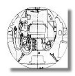
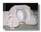
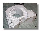
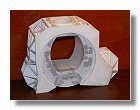
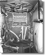
Before installing the thermal covering and details on the mid-section I decided to build the interior as I felt it would be easier to handle the model without having fragile parts on the outside. The first thing to do was again to draw some blueprints in order to have an accurate view of where all the hardware would place and their various sizes (figure 1). I was very fortunate to get access to some original blueprints, courtesy of the Northrop-Grumman History Center. I copied some parts of these blueprints, resized them to 1/24 and superimposed the drawing of the mid-section cabin as found in the mid-section structure blueprint. You may realize here that the mid-section cabin as built in the mid-section structure chapter (see figure 2e for instance) was actually larger than the correct cabin section, this picture shows the differences between both sections. The reason for this is that when I started to built this model I didn't have any blueprint of the interior of the LM so I had to guess size using reference photographs and in particular LM-noID-03. As you can see, knowing the diameter of the front section you can guess the size of the mid-section cabin. As shown in the mid-section blueprint the front section has a radius of 5.2 cm at 1/24 (49.13 inches for the real LM), however this is the oustside diameter of the LM front section while the inside front section cabin has a diameter of 46 inches (4.87 cm at 1/24). The reference photograph show the inside diameter and not the outside which then explains the error in the mid-section cabin dimensions.
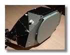
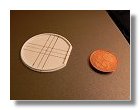
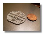
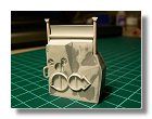
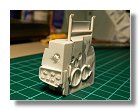
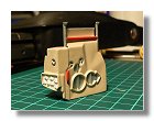
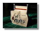
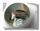
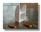
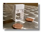
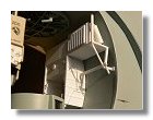
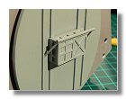
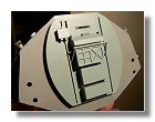
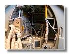
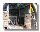
The first construction exercice was to build the back section bulkhead. As you can see on the mid-section blueprint, the aft limit of the pressurized cabin does not correspond to the limit between the mid and back sections which makes the mid-section cabin not as deep as the mid-section itself. At 1/24 the difference is 5.5 mm aft and 4.7 mm front. I built this aft bulkhead as shown in figures 2 and painted it in Luftwaffe blue. Because using the aft bulkhead would be sufficient to connect the back and mid sections, the attachement pins shown in figure 4c of the back section construction were not needed anymore.
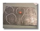
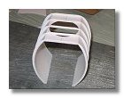
As shown on this figure and explained in the above sections, the mid-section cabin that I built was too large so I had to build a new structure that would eventually fit into the model. Since there is a 5.5 mm space between the aft section and the cabin I had to put some blocks made out of styren to be sure the cabin would be at the right position (see figures 3).
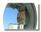
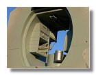
Overhead hatch and ascent engine cover
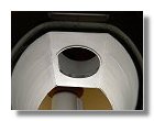
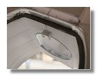
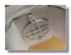
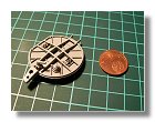
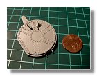
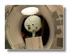
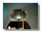
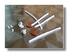
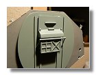
The first details to be built were the overhead hatch and the ascent engine cover (1/24 drawings are available here). These two parts were built in sequence to be sure the engine cover would not interfere while opening the hatch, the aim being to be able to open the overhead hatch to view the mid-section cabin. Construction process of the hatch is shown in figures 4 and the ascent engine cover in figure 5. Note that there is a latch on the ascent engine cover to fix the overhead hatch when open, however this latch could be declutched to offer more space in the mid-sestion cabin, in that case overhead hatch restraints were present on the hatch and on the aft wall of the mid-section cabin. This is clearcly visible on AP11-69-H-136. Note also that the following inscriptions are present on the overhead hatch :


The Lock and Unlock inscriptions are present on both sides of the hatch. The latch operation is also probably present on both sides however the rotation of the handle would be clockwise to unlock and counter-clokwise to lock, the inscription shown here is only for the cabin side of the hatch. At 1/24 this particular inscription is unreadable and I decided not to model it (sometimes you have to makes compromises). The "Pull to Dump" inscription refers to the cabin relief and dump valves, however this one is only present on the tunnel side of the hatch since the cabin valve has the word "open", "auto" and "close" directly written on the valve (unfortunatly too small to be visible here).
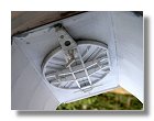
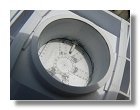
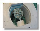
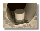
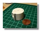
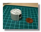
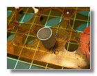
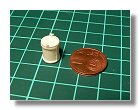
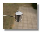
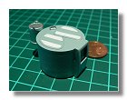
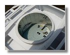
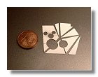
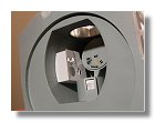
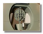
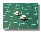
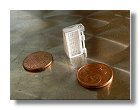
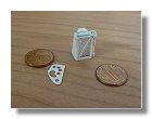
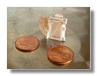
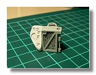
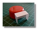
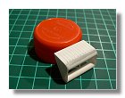
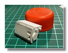
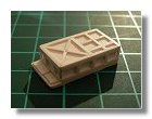
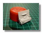
Construction of the Environmental Control System (ECS) LiOH cartridge was then started. The cartridge is used to absorb carbon dioxyde exhaled by the astronauts and thus make the atmosphere breathable. The same system is used on the Apollo command module and you may remember that the CM cartridge is square and the LM one is round which created a problem on the Apollo 13 flight. The LM cartridge was not sufficient to absorb all CO2 exhaled by the three astronauts during the trip back to Earth after the explosion of the service module (the CM ECS was not working since there was no more power in this module after the accident) and the astronauts, with a little help from Earth, had to design a way "to put a square peg in a round hole". Construction of the ECS LiOH cartridge is shown in figures 6 and assembly with the ascent engine cover is shown on figure 7.
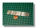
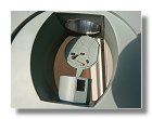
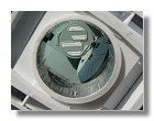
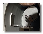
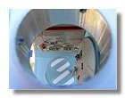
Prior to assemble the engine cover and the overhead hatch into the mid-section cabin I had to paint the interior in Luftwaffe blue and build the overhead tunnel, this way I didn't have any surprise while assembling the overhead hatch. The wall of the tunnel was made out of adhesive aluminium paper and the rivets made with a pounce wheel. Square holes in the aluminium paper correspond to the drogue latch. The bottom of the tunnel was painted in dark red to mimic the rubber seal for the hatch. The whole process is shown in figures 8. The engine cover and the overhead hatch were then installed into the mid-section cabin as shown in figures 9.
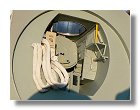
Environmental Control Subsystem (ECS) (figures 10)
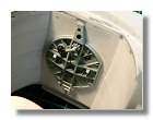
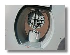
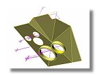
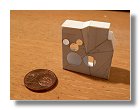
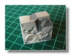
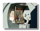
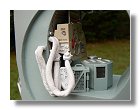
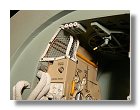
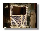
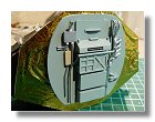
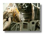
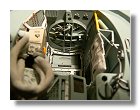
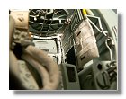
By building the ECS I was probably confronted to one of the same technical problems as the Grumman engineers. From photos I realized that the ECS had a very peculiar angular shape which I tried to reproduce. For this I used the blueprint of figure 1 for the basic dimensions and then started to draw the front part of the ECS in 3D using the free Alibre Express software. Using the 3D sketch (figure 10a) it was then fairly easy to measure all dimensions and angles of the various parts and start cutting styren (figure 10b). I then realized that the angular shape was meant to allow the overhead hatch to open inside the cabin. The margin to open the hatch is very small, specially at 1/24 and I had to make some adjustments to be sure the hatch would still open (see figures 10f). CO2 canister, suit circuit and cabin gas knob were then added as well as the oxigen control module on the front part of the ECS. The complete module was then painted in beige and blue luftwaffe (figure 10k), I then created some decals and attached the ECS to the mid-section using super glue (figure 10l). Suit isolation valves and corresponding hoses were then built as shown in figure 10o, electrical connections were added on the right wall of the mid-section cabin (figure 10q) and the suit flow controls system was then assembled completing construction of the Environmental Control System (figure 10r).
Cabin Recirculation Assembly & Water Module
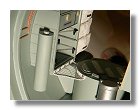
Also part of the ECS is the Cabin Recirculation Assembly and the Water module whose construction is depicted in figures 11. As you can see there are some differences between figure 11a and 11b. I realized that using only the blueprint of figure 1 the Cabin Recirculation Assembly was not wide enough, I then corrected this by removing the wired mesh part and replacing it by a larger one featuring a front knob I didn't see in the first instance. The water circulation module was also added, you can note that this module has a tilted position making it easier to operate by the astronauts standing up in the front section of the LM. Once painted it was then assembled onto the mid-section floor, the water module being slightly beyond the threshold of the mid-section cabin floor.
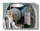
OPS, PLSS and storage compartments
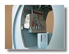
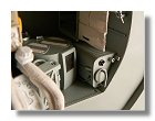
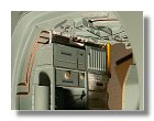
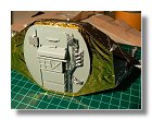
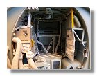
Having almost completed the right hand wall of the mid-section cabin (the back of the right hand wall being made along with the aft bulkhead), I started work on the left hand wall. This contains the storage compartments for one of the Portable Life Support System (PLSS), the two Oxygen Purge Systems (OPS), the onboard data files, the lunar overshoes (Moon boots) and food. Since the intention was to show the LM at the time of Neil Armstrong first step on the Moon, the storage compartments for PLSS and OPS are empty, the astronauts wearing their backpack at this time. Construction of the storage compartments is shown in figures 12. Once painted and assembled I added the Utility Light Assembly made out of fabrics and added them in front of the PLSS storage compartment.
Waste management section
The next step was building the The Lunar Module waste management system. Since there was no overboard dumping of wastes on the lunar surface. The urine subsystem in the Lunar Module consisted of in-suit urine containers , a urine transfer hose, a manually operated waste control valve, and a large waste fluid container (about 9 litres). Construction is depicted in figures 13.
Completing the ceiling, fixing the net
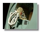
The ceiling of the mid-section needed to be completed. On the front part are a connection box and the PLSS downing attachments. On the back part are the cabin pressure valve and attachment bars for the safety net. figures 14 describe this process.
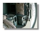
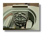
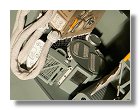
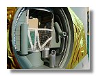
The walls and floor of the mid-section cabin are covered with tubes and wiring which need to be protected, a safety net was then attached to various parts of the mid-section systems like the engine cover or the Environmental Control Sub-system. Figures 15 describe the installation of this net and further details.
Completing the aft section and the safety net
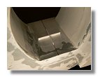
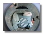
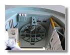
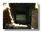
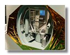
Because the aft part of the net interferes with fixture on the aft panel I had to work on the aft panel prior to completing the net. I then started work on the Apollo Guidance Computer (AGC) situated on the aft panel (figures 16). Knowing the precise location of the AGC I then completed the net (figure 17) and completed the aft panel (figures 18) and the aft part of the mid-section cabin (figures 19). Since the back section can be separated from the mid-section in order to look at the cabin, I covered the walls with 1/4 mil Kapton. This kind of kapton was only used on interior blankets as it is the case here. The final and complete mid-section can be seen in figures 20.
|
|
|
|
|
|
|
1 : Mid-section cabin blueprint - June 2007 |
2a, b : Back-section bulkhead - June 2007 |
3a, b, c, d : Cabin structure - June 2007 |
||||
|
|
|
|
|
|
|
3e, f : Cabin structure - June - July 2007 |
4a, b, c, d, e : Construction of the overhead hatch - July 2007 |
|||||
|
|
|
|
|
|
|
4f, g, h, i, j, k, l : Construction of the overhead hatch - August 2007 |
||||||
|
|
|
|
|
|
|
5a, b, c, d : Ascent engine cover - July - August 2007 |
6a, b, c : ECS LiOH cartridge - August 2007 |
|||||
|
|
|
|
|
|
|
7 : Assembly of engine cover and LiOH cartridge - August 2007 |
8a, b, c : Overhead tunnel - August 2007 |
9a, b, c : Assembly of engine cover and overhead hatch - August 2007 |
||||
|
|
|
|
|
|
|
10a, b, c, d, e, f, g : Environmental Control Sub-system (ECS) - August - September 2007 |
||||||
|
|
|
|
|
|
|
10h, i, j, k, l, m, n : Environmental Control Subsystem (ECS) - September 2007 |
||||||
|
|
|
|
|
|
|
10o, p, q, r : Environmental Control Subsystem (ECS) - September 2007 |
11a, b, c : Cabin Recirculation Assembly and Water Module - September 2007 |
|||||
|
|
|
|
|
|
|
11d, e, f : Cabin Recirculation Assembly and Water Module - September 2007 |
12a, b, c, d : OPS, PLSS and storage compartments - September - October 2007 |
|||||
|
|
|
|
|
|
|
12e, f, g : OPS, PLSS and storage compartments - October 2007 |
13a, b, c, d : Waste management section : October 2007 |
|||||
|
|
|
|
|
|
|
13e : Waste management section : October 2007 |
14a, b : Detailling the ceiling - October 2007 |
15a, b, c, d : Installing the safety net - October 2007 |
||||
|
|
|
|
|
|
|
16a, b, c : Apollo Guidance Computer - October 2007 |
17 : Completing the net - October 2007 |
18a, b, c : Completing the aft bulkhead - October 2007 |
||||
|
|
|
|
|
|
|
18d, e : Completing the aft bulkhead - November 2007 |
19a, b : Completing the aft part of the mid-section - November 2007 |
20a, b, c : Complete mid-section cabin - November 2007 |
||||
|
|
|
||||
20d, e, f : Complete mid-section cabin - November 2007 |
||||||
Photographs and blueprints by Vincent Meens, June - November 2007
Front page - Ascent stage mid-section structure - Back-section structure - Back-section details - Mid-section cabin - Mid-section details - Front-section structure
Forward-section cockpit - Forward section details - Completed ascent stage - Descent stage - Moon base - Completed model