Front page - Ascent stage mid-section structure - Back-section structure - Back-section details - Mid-section cabin - Mid-section details - Front-section structure
Forward-section cockpit - Forward section details - Completed ascent stage - Descent stage - Moon base - Completed model
The Ascent Stage Mid-Section
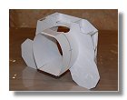
The mid-section of the ascent stage contains a part of the pressurized cabin, the ascent engine and the main fuel tanks. The fuel tanks and the equipments are protected by anodized aluminium plates that are fixed onto a truss. The 1/48 models show the angular shape of the mid section as a regular body while photos of actual LMs show that the plates are not completely contiguous. At 1/24 it would be easier to show this feature.
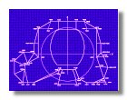
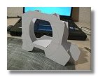
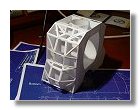
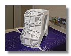
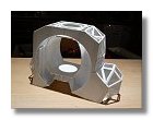
I first draw a blueprint of the Ascent stage mid-section in Figure 1. I decided to cut 4 sections of the ascent stage in 1 mm styren sheets. The first page of the blueprint gives the dimension in cm of the first 2 front sections while the second page gives the dimensions of the 2 back sections. You will note that the middle sections are slightly bended in the upper part of the pressurized cabin. The first two front sections were united using 1 mm styren, I then used styren rods to build the truss and added the walls of the pressurized cabin thus facilitating the alignment of the remaining sections. A large hole was made in the upper part of the pressurized cabin to allow for the tunnel to be built later on. The last two back sections were then added and the truss completed. The whole process is shown in Figures 2.
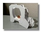
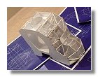
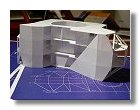
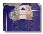
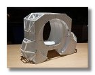
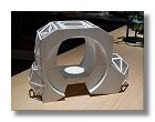
I then had to prepare the mid-section for applying the various anodized aluminium plates and the kapton layers. The kapton layers are to be applied on the bottom side of the mid-section, I then glued 0.25 sheets of styren on which the kapton will be sticked later on as shown in figures 3. Note that a hole is made in the middle of the section to allow for the engine bell to be installed later-on. For the anodized aluminium plates, the rods were not sufficient to apply them correctly on the structure. I then had to apply some styren bands of about 2/3 mm wide on which the plates will be sticked later-on as shown in figures 4. For both processes shown in figures 3, 4 and 5 things have not to be clean and perfect, it is only a support onto which either the kapton foil or the aluminium plates are to be installed.
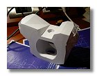
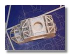
Later-on while as I was starting to draw a blueprint for the mid-section cabin, I came to realize that I had too much space. After fitting the PLSS and OPS the depth of the cabin was too deep even with the LM guidance computer in the back of the cabin. My mistake was that the depth of the cabin is somewhat smaller than the exterior depth of the mid section. Indeed the front section cabin goes a bit inside the mid section. At 1/24 scale this is about 8 mm less depth. I discovered this because since I had the right measurements of the PLSS and OPS and they are both fitted one close to each other, there was too much space remaining between them. So I modified the mid-section structure blueprint and modified the model. Modifications to the mid-section structure is shown in figures 6.
|
|
|
|
|
|
1 : Mid-section blueprint - December 2006 |
2a, b, c, d, e : Building the structure of the ascent stage - December 2006 |
||||
|
|
|
|
|
|
2f : Building the structure of the ascent stage - January 2007 |
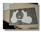
3a, b : Preparing the bottom part of the mid-section - February 2007 |
4a, b: Preparing the side parts of the mid-section - |
5a : Preparing the upper part of the mid-section - February 2007 |
||
|
|
|
|
|
|
|
5b : Preparing the upper part of the mid-section - February 2007 |
6a, b, c : Transition between Front section and Mid section cabins - May 2007 |
|
||
Photographs and blueprints by Vincent Meens, December 2006 - May 2007
Front page - Ascent stage mid-section structure - Back-section structure - Back-section details - Mid-section cabin - Mid-section details - Front-section structure
Forward-section cockpit - Forward section details - Completed ascent stage - Descent stage - Moon base - Completed model