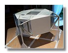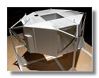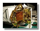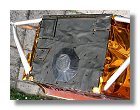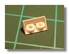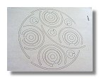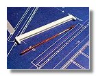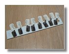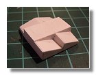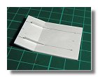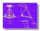
1 : Descent stage blueprint - August 2009
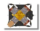
2 : Descent stage coating - October 2009
Front page - Ascent stage mid-section structure - Back-section structure - Back-section details - Mid-section cabin - Mid-section details - Front-section structure
Forward-section cockpit - Forward section details - Completed ascent stage - Descent stage - Moon base - Completed model
The Descent Stage
|
|
|
1 : Descent stage blueprint - August 2009 |
2 : Descent stage coating - October 2009 |
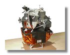
 The descent stage is the unmanned portion of the LM. It consists of two parallel beams arranged in a cruciform with a deck on the upped and lower surfaces. A
four-legged truss at the ends of each pair of beams serves as a support for the LM in the spacecraft launch adapter of the SIVB stage of the Saturn V launcher
and as attachment point for the main strut of the landing gear. Compartments formed by the descent stage structural arrangement house LM subsystems, the center
compartment houses the LM descent engine while the aft and fore compartments house the oxidizer tanks and the side compartments the fuel tanks. The areas
between the main beams are referred as quadrants and are numbered from 1 to 4, quadrant 1 is located at the CDR position and subsequent quadrant are
numbered anticlockwise. On Apollo 11 Quadrant 1 housed the high gain S-band antenna, however since the Apollo 11 Moon walk was quite short and the
transmission through the LM high gain S-band antenna correct, this antenna was not deployed and is still stored in the LM-5 descent stage. Quadrant 2 helds the
Scientific EQuipment (SEQ) bay containing the Early Apollo Scientific Experiment Package (EASEP); Quadrant 3 houses helium and oxygen tanks and Quadrant
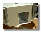
4 water and oxygen tanks as well as the Modular Equipment Storage Assembly (MESA). MESA was opened by Neil Armstrong while on the porch of the
descent stage revealing a TV camera for the earthling to view the first step on the Moon. Since I intend to represent that first step, this MESA will then be open on
the model.
The descent stage is the unmanned portion of the LM. It consists of two parallel beams arranged in a cruciform with a deck on the upped and lower surfaces. A
four-legged truss at the ends of each pair of beams serves as a support for the LM in the spacecraft launch adapter of the SIVB stage of the Saturn V launcher
and as attachment point for the main strut of the landing gear. Compartments formed by the descent stage structural arrangement house LM subsystems, the center
compartment houses the LM descent engine while the aft and fore compartments house the oxidizer tanks and the side compartments the fuel tanks. The areas
between the main beams are referred as quadrants and are numbered from 1 to 4, quadrant 1 is located at the CDR position and subsequent quadrant are
numbered anticlockwise. On Apollo 11 Quadrant 1 housed the high gain S-band antenna, however since the Apollo 11 Moon walk was quite short and the
transmission through the LM high gain S-band antenna correct, this antenna was not deployed and is still stored in the LM-5 descent stage. Quadrant 2 helds the
Scientific EQuipment (SEQ) bay containing the Early Apollo Scientific Experiment Package (EASEP); Quadrant 3 houses helium and oxygen tanks and Quadrant
4 water and oxygen tanks as well as the Modular Equipment Storage Assembly (MESA). MESA was opened by Neil Armstrong while on the porch of the
descent stage revealing a TV camera for the earthling to view the first step on the Moon. Since I intend to represent that first step, this MESA will then be open on
the model.
Descent stage structure
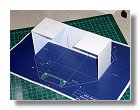
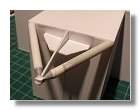
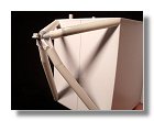
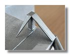
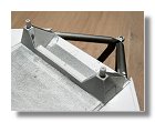
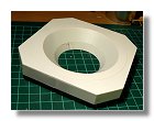
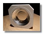
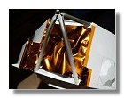
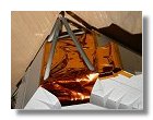
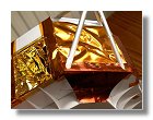
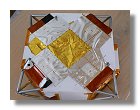
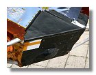
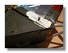
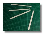
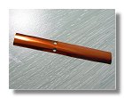
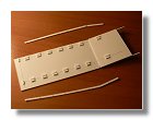
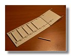
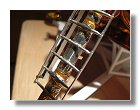
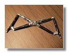
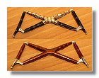
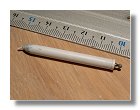
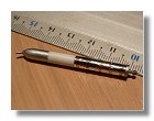
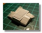
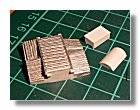
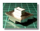
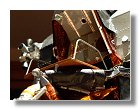
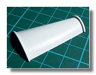
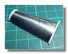
I started building the descent stage by making the cruciform (figures 3), this was made of 1 mm styrene to be able to get a light and rigid structure. I also included preliminary forward attachment points to check the assembly of ascent and descent stages. I then installed the landing gear outrigger assembly at the end of each pair of beams as shown in figures 4, I started by the SLA attachment point by using 5 styrene strata (figure 4a), I then built a temporary support structure (figure 4b) to be sure the SLA attachment point was at its exact location, this structure and and the attachment point were simply fixed using double faced adhesive tape so that it could easily be removed. The truss was then assembled around the SLA attachment point (starting in figure 4c). You can note that each strut differs slightly from the one shown in the blueprint, in particular they have a constant diameter. The reason being that the conical shape of the struts will not be visible since each of them (except around the SLA attachment point) will be covered by either black pyromark aluminium or kapton foil. Having the struts made out of constant diameter styrene rods was a way to get a more rigid structure.
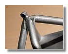
The next step was to built the ascent stage attachment points (see figures 5). The forward points were a bit more difficult to construct because of their angular shape, on the opposite the aft points were quite easy and didn't need any extra care since in the end all points will be covered by kapton and beta cloth. Once this was done I checked the assembly of the ascent and descent stages as shown in figure 5g.
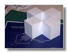
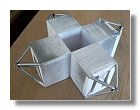
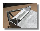
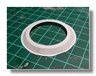
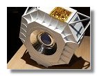
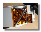
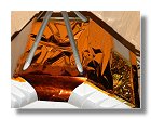
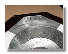
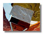
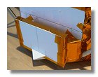
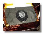
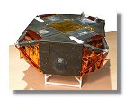
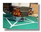
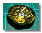
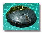
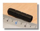
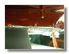
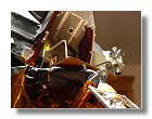
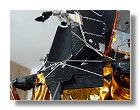
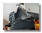
I then built the 4 quadrant shapes. It is important to realize that, except in a certain measure for Quadrant 2, there is no wall on the real LM and that the shape of all quadrants is really made out of the kapton and inconel covers. However for a model, and in order to apply the kapton and black covers, hard plastic walls were necessary. Since everything in the end will be covered by kapton and inconel (black aluminium paper for the model) these walls will completely disappear. Construction of the 4 quadrants is shown in figures 6, figures 7, figures 8 and figures 9. On Quadrant 4 (figures 9) I also had to build the MESA, its various components were very basically done (figure 9b) since the MESA is almost entirely covered with 0.5 mil kapton, only showing the lens of the TV camera. There is no wall supporting the 0.5 mil kapton inside Quadrant 4, by inserting the MESA covered with extra kapton I was then able to shape the kapton inside Quadrant 4 (see figure 9e), you very clearly see there the difference in color between 0.5 and 2 mil kapton.
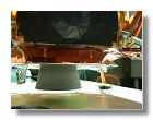
Prior to apply the thermal blankets I completed the bottom of the descent stage (figures 10). Only the thermal shield was applied on the conical shape around the engine since it would have been difficult to apply it with the main bottom structure installed.
|
|
|
|
|
|
|
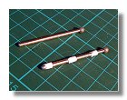
3a, b : Building the cruciform - September 2009 |
4a, b, c, d, e : Landing gear outrigger assembly - September 2009 |
|||||
|
|
|
|
|
|
|
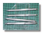
4f, g : Landing gear outrigger assembly - September - October 2009 |
5a, b, c, d, e : Ascent stage attachment points - October - November 2009 |
|||||
|
|
|
|
|
|
|
5f, g : Ascent stage attachment points - November 2009 |
6a, b, c : Quad 1 construction - November 2009 |
7a, b : Quad 2 construction - November 2009 |
||||
|
|
|
|
|
|
|
8a, b, c, d : Quad 3 construction - November 2009 |
9a, b, c : Quad 4 construction - November 2009 |
|||||
|
|
|
|
|
|
|
9d, e, f, g : Quad 4 and MESA construction - November 2009 |
10a, b, c : Bottom of the descent stage - December 2009 |
|||||
|
|
|
|
|
|
|
|
|
10d, e, f, g : Bottom of the descent stage - December 2009 |
|
|||
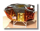
Descent stage coating
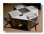
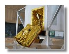
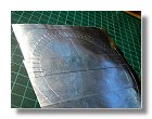
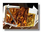
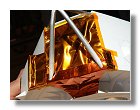
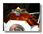
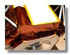
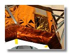
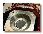
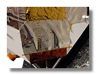
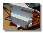
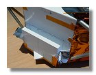
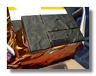
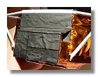
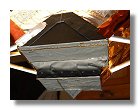
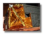
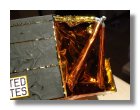
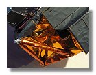
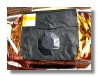
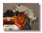
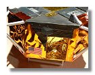
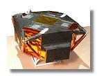
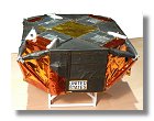
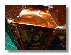
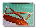
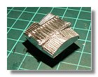
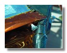
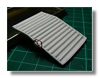
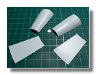
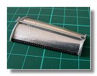
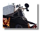
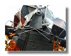
The 2 mil kapton was fixed onto each bulkhead and quad (mainly Quad 4). It would have been difficult due to the rigidity of the kapton to use double sided adhesive tape to fix the kapton onto the structure. Instead I used mini nails which I found at Micro Mark. Then using a piece of kapton slightly larger than the area to cover I was able to create the ripple effect typical of the LM descent stage (see figures 11). I then applied the 5 mil kapton underneath the descent stage, because of the rigidity of the kapton, it was applied in eight parts that were joined by adhesive kapton (see figures 12). The bottom stage coating was then completed by applying adhesive aluminium for the engine thermal shield (see figures 13). The top coating was then applied around each bulkhead, starting with the aluminium colored blankets and finishing with the 5 mil kapton (see figures 14).
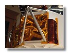
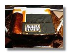
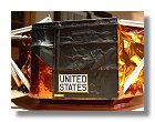
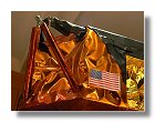
Final coating of the descent stage was for the 4 quadrants and the landing gear outrigger assembly. I started with Quad 1 (figures 15), Quad 2 (figures 16) and when two consecutive quads were completed with the outrigger assembly. For Quad 1 the UNITED STATES logo was printed using a laser color printer. For Quad 2, since I built it uncorrectly (see the difference in shape between the blueprint and figure 7b), it was therefore necessary to remove some parts of the styrene before applying the coating (figures 16), also note that the ascent stage attachment point is covered with white beta cloth as for the forward attachment points (figure 14d).
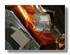
Coating the landing gear outrigger assembly was not very easy but managable with care and time, I first put the vents in place and covered the outrigger assembly with 1/2 mil kapton, the lower outrigger was then covered with 5 mil clear kapton (a fashion only present for LM-5, clear kapton was not present for subsequent LMs) and the upper outrigger with black paper to mimick the black pyromark (see figures 17). I then coated Quadrant 3 (figures 18), the -Z landing gear outrigger (figure 19). Quadrant 4 (figures 20), and finished with the +Y and +Z landing gear outriggers. for the +Y outrigger assembly I made sure not to forget the "+Y Do-Hicky," AKA the Lower Umbilical between the LM and the SLA (figures 21). Final coating of the descent stage is shown on figures 22.
|
|
|
|
|
|
|
11a, b, c, d, e, f : Application of 2 mil kapton - December 2009 |
12a : Application of 5 mil kapton underneath the descent stage - January 2010 |
|||||
|
|
|
|
|
|
|
12b, c, d, e, f, g, h: Application of 5 mil kapton underneath the descent stage - January 2010 |
||||||
|
|
|
|
|
|
|
13a, b, c : Final construction of the thermal shield - February 2010 |
14a, b, c, d : Top coating - February - March 2010 |
|||||
|
|
|
|
|
|
|
15a, b, c : Quad 1 coating - March 2010 |
16a, b, c, d : Quad 2 coating - March 2010 |
|||||
|
|
|
|
|
|
|
16e, f, g : Quad 2 coating - March 2010 |
17a, b, c, d : Landing gear outrigger assembly (-Y) - March 2010 |
|||||
|
|
|
|
|
|
|
18a, b, c, d, e : Quad 3 coating - March 2010 |
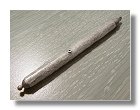
19 : Landing gear outrigger assembly (-Z) - March 2010 |
20a : Quad 4 coating - March - April 2010 |
||||
|
|
|
|
|
|
|
20b : Quad 4 coating - March - April 2010 |
21a, b, c, d : Landing gear outrigger assembly (+Y) - April 2010 |
22a, b : Descent stage final coating - April 2010 |
||||
|
|
|
|
|
|
|
|
22c, d, e : Descent stage final coating - April 2010 |
|
||||
Landing gear
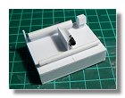
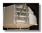
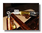
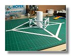
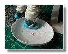
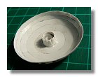
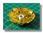
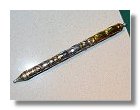
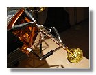
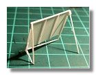
Having completed the descent stage coating I started the landing gear. Because I wanted the gear and the footpads to rest exactly at their correct position I first had to build a structure which would allow me to precisely position the descent stage on its center and the footpads 17,73 cm from it. The structure is shown on figures 23, as you can see a cylinder is inserted in the descent engine location while pins are located at the footpad locations. Using the blueprint developped by Mattias Malmer who is also building an exact replica of LM-5 at 1/24, I first built the LM footpads as shown in figures 24.
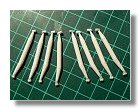
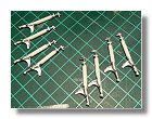
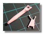
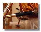
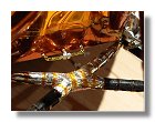
The next step was to build the LM primary struts, this was done in styrene for the main cylinder, however to ensure a firm connection between the strut and the footpad I used a spherical drill, the sphere having the right diameter to connect with the footpad. The struts were then covered with some thin bubblewrap paper and 0.5 mil kapton (one part showing the gold side and the other one the chrome side) before putting the 5 mil kapton in place. Then I put the kapton tape giving it the wrapped aspect. Note that the location of the kapton tape is different for each primary strut as shown on the blueprint (figures 25).
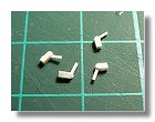
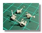
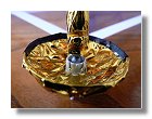
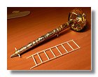
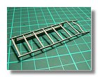
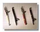
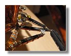
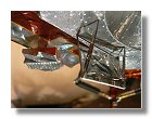
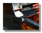
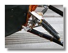
The final steps of completing the primary struts were to build the uplock mechanism that maintains the landing gear in folded position during liftoff (figures 26), the probe locking mechanism that maintains the landing probes into position during liftoff (figures 27), the pad restraining straps (figure 28) and the ladder (figures 29). The landing probe on landing gear +Z was removed while the LM was already installed into the Saturn V booster in order to avoid a possible obstacle for the astronaut while descending the ladder, so although the probe is not there the probe locking mechanism is still present on this gear. It is also present on LM-6 (Apollo 12) but disapeared on further LMs. While building the ladder I represented it with the plaque still hidden (figure 29h), my intention being to represent the Apollo 11 landing while Aldrin is descending the ladder and is photographed by Armstrong, at this stage the plaque was not yet unveiled. Figure 30 shows the model starting to be closer to the finished item.
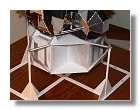
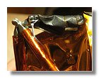
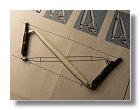
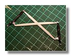
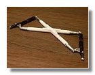
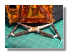
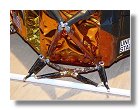
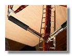
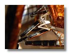
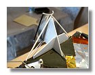
Things started to get close to the LM standing on its own feet, I then built the truss assembly together with the X-brace and the uplock struts (see figures 31). Once assembled and covered with the proper blankets the truss assembly was fixed onto the hinges using super glue, I used a 6 mm rod to maintain it at the proper heigh (figures 31n) before fixing the secondary struts. As for the primary struts I used a sperical drill as an attachment between the primary and the secondary struts, the black cover was made out of black paper and while the descent stage was sitting on its support structure (see figure 23b) I could adjust and fix the secondary struts to the primary strut and the truss assembly, the whole process is shown on figures 32.
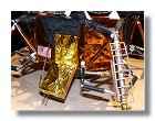
The final process was to build the downlock mechanism composed of a down-lock latch, a down-lock cam and a crank and link assembly covered with a titanium guard plate. All pieces were made out of styrene. That required a lot of time, patience and adjustment (see figure 33). Finally after about eight months of work I completed the four landing gears (figure 34).
|
|
|
|
|
|
|
23a, b, c : Descent stage support structure - April 2010 |
24a, b, c, d : LM footpads - April 2010 |
|||||
|
|
|
|
|
|
|
24e, f, g : LM footpads - April - July 2010 |
|
25a, b, c, d : LM primary strut - April - June 2010 |
||||
|
|
|
|
|
|
|
25e, f, g, h, i : LM primary strut - April - July 2010 |
26a, b : Uplock mechanism - July - August 2010 |
|||||
|
|
|
|
|
|
|
27a, b : Probe locking mechanism - September 2010 |
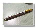
28 : Pad retraining straps - September 2010 |
29a, b, c, d : Construction of the ladder - September 2010 |
||||
|
|
|
|
|
|
|
29e, f, g, h : Construction of the ladder - September 2010 |
30 : LM-5 - September 2010 |
31a, b : Truss Assembly - September - October 2010 |
||||
|
|
|
|
|
|
|
31c, d, e, f, g, h, I : Truss Assembly - September - October 2010 |
||||||
|
|
|
|
|
|
|
31j, k, l, m, n : Truss Assembly - October - November 2010 |
32a : Secondary strut - November 2010 |
|||||
|
|
|
|
|
|
|
|
32b, c, d, e, f : Secondary strut - November 2010 |
33a, b : Down-lock mechanism - November - December 2010 |
||||
|
|
|
|
|
|
|
33c, d, e, f : Down-lock mechanism - November - December 2010 |
34a, b : Completed landing gear - December 2010 |
|
||||
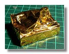
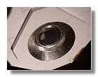
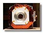
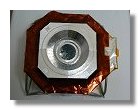
Descent engine bell (see figures 35)
As for the ascent engine, the descent engine bell was primarily made of truncated cones of different diameters and angles. The pattern for the engine can be found in the various details sheet. It was then sanded and smoothed using putty. The color of the engine was a concern as some photos show it with two different colors (such as AS11-44-6574). In fact these two different tones are not visible on the pictures taken on the Moon and are due to a difference of reflection between two seams of the engine during the LM inspection flight. The color I used was Humbrol 140 which I found close enough to the real color. Interestingly I found a real difference between the bottom part and the upper part of the engine bell on some pictures such as AS17-147-22517, that difference is also visible on LM-10 and LM-11. It appears that the J-Series DPS engine bells were constructed differently than the G- and H-series. The J-series units were elongated (stretched) to try and squeeze a little extra specific impulse out of them. It is that stretched part that has a lighter grey. Many thanks to Karl Dodenhoff and Paul Fjeld for helping me on solving the intricacies of the LM descent engine. For those who want to build an LM for either Apollo 15, 16 or 17, don't forget then that the DPS engine bell is almost at ground level.
|
|
|
|
35a, b, c, d : Descent engine bell - December 2010 |
|||
Landing radar
The landing radar was used during descent to measure the heigth of the lunar module and give indication on the horizontal and vertical speeds. This was of critical importance to control the attitude of the LM and the engine thrust to make sure that at the end of the descent there was no more horizontal velocity and that the vertical velocity did not exceed 3 to 4 feet per second. During most of the descent the LM was pitching up, the engine thrust could then be divided in two components to reduce both horizontal and vertical speeds, for that reason the landing radar could be tilted in order to point vertically to the lunar surface. However since the last 100 ft descent was completely vertical the LM landing radar was not tilted on the lunar surface. Figures 36 shows the building process, the radar was covered with bare metal foil to give its shiny appearance.
|
|
|
|
|
|
|
|
36a, b : Landing radar - January 2011 |
|||||||
Small details
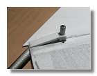
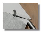
Small details needed to be done prior to complete the descent stage with the egress platform and the plume deflectors. The first details were the chock mount (figure 37) that were used to maintain the landing gears during launch and prior to extending them. These chock mount were covered with 5 mil kapton, however considering its small size it seemed difficult to use real kapton here because of its stiffness. Instead I painted them noting that Humbrol 55 matched almost perfectly the 5 mil kapton color. A good trick for LM builders would be to use aluminium or chocolate paper and paint it with Humbrol 55 to mimick the 5 mil kapton.
As for the ascent stage propellant drains and helium vent tubes were present on the descent stage. The propellant drains were placed on the bottom of quadrant 3 (figures 38) while the helium overboard vent tubes were at the top of bulkheads -Z and +Y and at the bottom of quadrant 3 (figures 39).
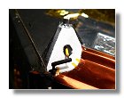
The landing gear uplock mechanisms were completed, a first part was done earlier and was attached to the landing gear (figures 26), a second part was attached to the descent stage main frame. A guillotine would severe the link between both parts and release the landing gear (figures 40). The MESA was slightly modified (more 2 mil kapton on the sides and the addition of straps) and finally deployed to complete the small details of the descent stage (figure 41).
|
|
|
|
|
37 : Landing radar chock mount - January 2011 |
38a, b : Propellant drains - January 2011 |
39a, b : Helium overboard vent tubes - January 2011 |
||
|
|
|
|
|
39c : Helium overboard vent tubes - January 2011 |
40a, b : Landing gear uplock mechanism - January 2011 |
41 : MESA deployment - January 2011 |
|
|
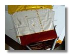
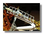
Egress platform (figures 42)
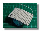
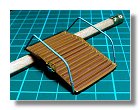
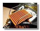
The egress platform was used by the astronauts as its name indicates to egress the ascent stage. When the astronauts got out of the main hatch they were literally ramping on the floor, totally unable to see where they were going. Picture AS11-40-5863 is a good example of the difficult way out of the lunar module. The large platform with its corrugated floor was able to sustain the astronaut feet while the large handrails helped him to secure its position prior to reaching the ladder.
The platform was made out of 0.25 mm styrene with 1 mm rods to make the corrugation. The floor was painted with red brick humbrol 70 while the corrugations were painted using light brown humbrol 9. For the handrails I used 0.9 mm wire. I didn't forget to build the yellow handle and the cable system that were used open the MESA.
|
|
|
|
|
42a, b, c, d, e : Egress platform - April 2011 |
||||
|
|
|
|
|
42f, g, h, i, j : Egress platform - April 2011 |
||||
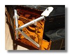
Plume deflectors
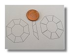
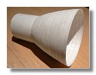
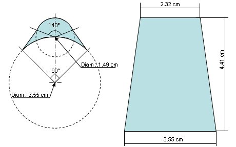 The plume deflectors created a challenge as their shape is not a part of a simple cone. As shown on the figure on the left the
bottom part of the deflector is a 90° section of a 3.55 cm diameter circle while the upper part is not a 90° section but a 140°
section of a 1.49 cm diameter circle. To be part of a simple cone both sections needed to be either 90° or 140°. I choose to
make a cone where each plume déflector would be a 90° section of that cone and decided to distort somehow the upper part.
The plume deflectors created a challenge as their shape is not a part of a simple cone. As shown on the figure on the left the
bottom part of the deflector is a 90° section of a 3.55 cm diameter circle while the upper part is not a 90° section but a 140°
section of a 1.49 cm diameter circle. To be part of a simple cone both sections needed to be either 90° or 140°. I choose to
make a cone where each plume déflector would be a 90° section of that cone and decided to distort somehow the upper part.
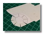
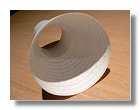
However the cone could not have an upper diameter of 1.49 cm but rather a diameter of 140/90*1.49 = 2.32 cm as shown on the figure. I made the plume deflector out of 0.3 mm styrene and bent them, then using 3.55 cm diameter and 1.49 cm diameter circles (figure 43b) I managed to create the correct shape of the deflector (figure 43c)
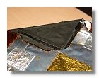
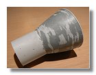
The back side of the deflector was then covered with adhesive aluminium paper (figure 43d) while the front side was covered with black painted aluminium paper, for each part I used a paper pattern that can be found in page 2 of the "various details" pdf file. I also made sure not to forget to make the small rivets using a pounce wheel and to wrap a bit he black aluminium paper to give it its crinkle effect.
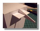
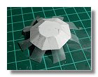
The final step was to fix the plume deflector onto the descent stage. For this I made a support structure out of 5 mm styren to position the deflector, this structure was simply fixed onto the descent stage using double sided adhesive tape so it could easily be removed after the support rods were fixed (figure 43g).
|
|
|
|
|
|
43a, b, c, d, e, f : Plume deflectors - May - June 2011 |
|||||
|
|
|
|
|
|
43g, h, i, j, k : Plume deflectors - June 2011 |
|
||||
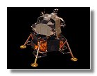
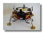
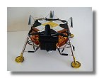
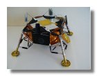
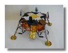
Completed descent stage
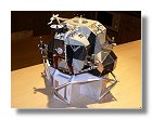
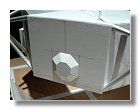
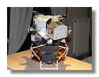
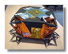
With the completion of each deflector plume that also meant the completion of the descent stage (figures 44) and the lunar module after four and a half years of work . However to make it better I needed to create a lunar scenery and a new chapter to this web site.
|
|
|
|
44a, b, c, d : Completed descent stage - June 2011 |
|||
Front page - Ascent stage mid-section structure - Back-section structure - Back-section details - Mid-section cabin - Mid-section details - Front-section structure
Forward-section cockpit - Forward section details - Completed ascent stage - Descent stage - Moon base - Completed model