Front page - Ascent stage mid-section structure - Back-section structure - Back-section details - Mid-section cabin - Mid-section details - Front-section structure
Forward-section cockpit - Forward section details - Completed ascent stage - Descent stage - Moon base - Completed model
The Ascent Stage Forward-Section Cockpit
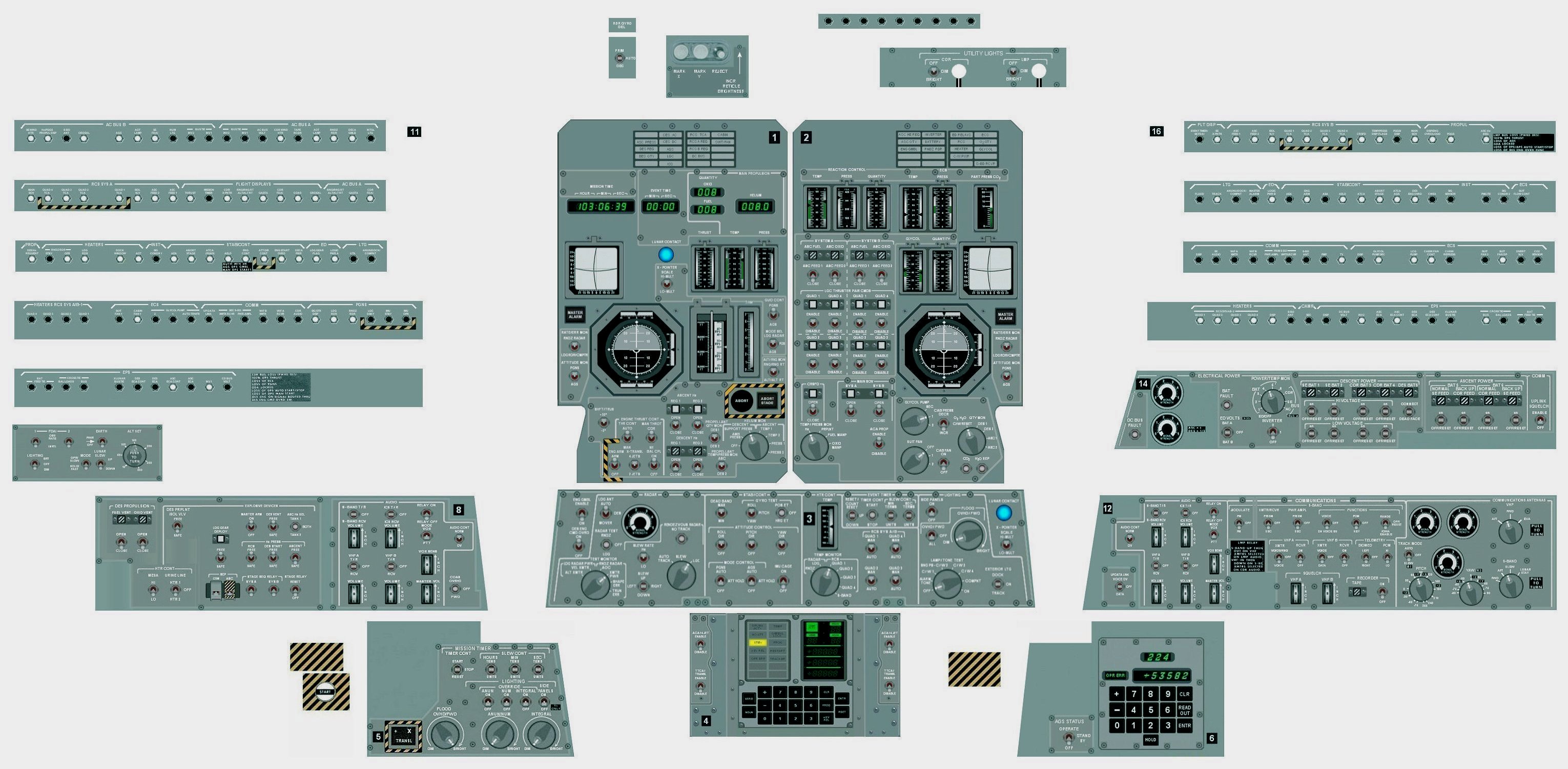
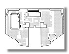
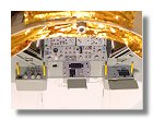
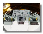
After completing the mid-section and the forward section structure I continued working on the interior of LM-5. The first details to be added were the main instrument panels between the two main windows (Panels 1, 2 and 3). In order to be as precise as possible I first had to make blueprints of the arrangement of the various instruments and an other blueprint showing in detail the instrument panels. I was very fortunate to get access to some original blueprints, courtesy of the Northrop-Grumman History Center. I copied some parts of these blueprints, resized them to 1/24 and superimposed the drawing of the forward-section cockpit (see figure 1). For the instrument panels I started with a screen copy of the LM instrument panels from the Orbiter simulation software kindly provided by Thorsten Brand. From this original drawing I created a drawing of all instrument panels, copying and pasting knobs and switches and trying to keep the relative scale between all panels. The final result is shown on figure 2.
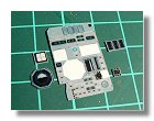
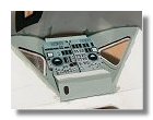
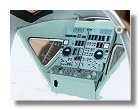
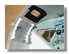
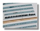
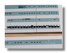
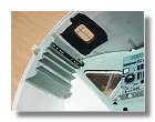
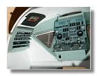
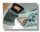
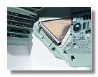
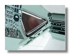
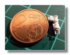
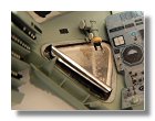
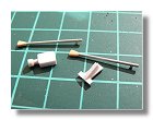
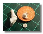
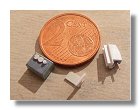
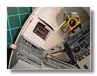
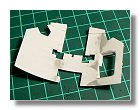
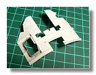
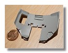
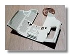
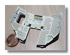
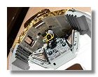
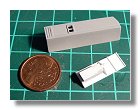
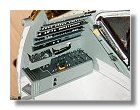
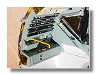
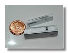
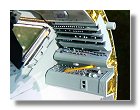
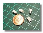
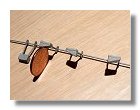
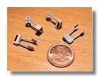
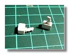
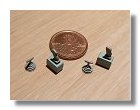
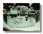
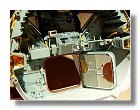
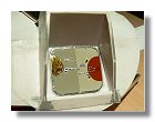
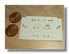
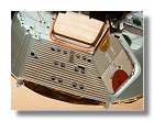
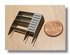
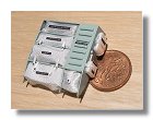
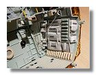
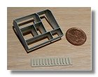
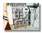
For panels 1, 2 and 3, I resized the instrument panel drawing to 1/24 to create a decal. The biggest difficulty was probably to print a color that matched the luftwaffe blue of the cockpit, so I had to make several attempts for this. I then cut several parts of Panels 1 and 2 where the instruments appear embossed and put the decal on various thickness of styren (X-pointers and FDAI balls are on 0.25 mm styren and gauges on 0.4 mm styren). These secondary panels were then put on each main panels. I used small pieces of wire to create the switches and made the knob using a 2 mm diameter punch (see figures 3). The next step was to make panels 11 and 16 situated on the side walls (figures 4). Making the circuit breakers was quite a difficult task, each one was made of 0.6 mm diameter and 1 mm long rod, since each rod could not be identical in length I first had to glue each one onto the panel pattern (figure 4c) and sand them all to make sure they all had the same length (figure 4d). Depending on the postion of each circuit breaker they were painted black or white. The color was provided on the LM checklist (pages 34 and 35) which the astronauts taped on the LM wall above panels 11 and 16 (see AS11-37-5528).
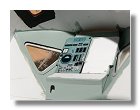
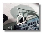
The next step was to detail the main windows. I first had to make the shades using black and adhesive aluminium papers. The shades were rolled and put into position using double adhesive tape. I had to make sure that the inside of the shade was black and the outside aluminium, shades are found on the two main windows and the rendezvous window. I then made the COAS (Crewman Optical Alignment Sight). I used a picture where I had a 3 inches scale that allowed me to make a sketch with the proper dimension (see page 5 of the various detail sheet), I then made details for the crash bar and the 16 mm camera and after installing them I completed detailling the windows by installing the glareshield (see figures 5 for the whole process).
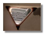
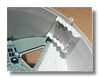
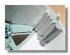
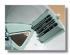
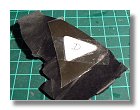
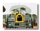
Prior to make the roof padding I built the Alignment Optical Telescope or AOT. The only difficulty here was to build the AOT guard, I made it out of 0.8 mm styren rods. I thought at the beginning to build, paint and fix it to the LM roof. However, even if bending the rod was easy, keeping it in place proved to be difficult, so I decided to build and fix it to the roof at the same time, and painted it in blue luftwaffe and yellow later (see figures 6). It was then ready for building the roof padding. Since the shape is complicated and many openings are necessary for the rendezvous windows, lights and control panels, the padding was made out of several parts starting from panel 11 to panel 16. In the end, for the small holes covering most of the padding I first made a pattern of what needed to be covered (figure 7e) and the series of holes themselves were made with decals (see figures 7). Note that on each side of the padding are pages of the lunar surface checklist (pages 34 and 35) which the astronauts taped on the LM wall above panels 11 and 16 (see AS11-37-5528).
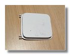
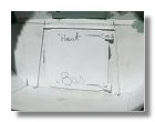
Then followed panels 8 and 10 (left side panels, see figures 8) and panels 12 and 14 (right side panels, see figures 9). Before finalizing the control panels I had to define exactly the limit between the control panel line and the main hatch. The best way to do it was to make a rough shape of the hatch and place it onto the forward cockpit before starting the last panels (figures 10). Detailled construction of the hatch would follow later-on.
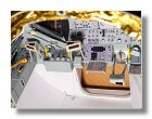
I then built the final panels starting with the armrests (figures 11), the panels (figures 12) and the hand controllers (figures 13). For the hand controllers I used different sizes of 0.25 mm styrene parts that were glued one onto the other to mimic the rubber base of each controller. The final assembly of all these components is shown on figures 14. I decided to show the armrests in stowed position at the CDR place and in extended position at the LMP place.
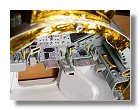
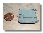
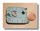
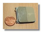
I then completed the front wall by building the front hatch section. I first made all details on the wall and then used some fine cotton thread to make the cables that are used to restraint the standing astronauts during landing and take-off. Construction of the main hatch required some carefull examination of the main panel color (panel 3). This panel is actually made of two panels, both are chromic acid anodized but one is definitly lighter than the other (see A11-40-5868). When I first covered the rear and mid sections of the ascent stage I used Humbrol 40 to mimic the color tof the aluminium 5056-H191 chromic acid anodized panels. During this process there was an occurence when I didn't mix the paint well enough, the result was a lighter tone, I didn't use the sheet and was lucky to keep it and used it for the hatch. Contruction of the main hatch section is depicted in figures 15.
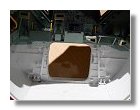
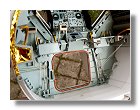
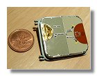
The final contruction phases were for the floor and side stowage compartments. For the floor I simply used 0.05 mm styrene parts that were glued onto the main sheet to mimic the details and velcro floor (figures 16). For the side stowage it was not easy to find good reference as LM-5 was a G mission and not a H or J mission. This means that she was not fitted for long duration stay on the Moon, for instance there was no hammock on board and it is probable that the configuration of the compartments was close to that of LM-3 and LM-4. I found a reference drawing from the 1968 LM news reference document that I then used in conjunction with figure 1 for the dimensions. This diagram can be found here and contruction of the side stowage is found in figures 17 and 18.
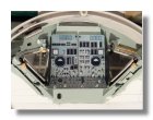
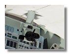
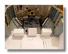
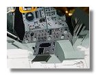
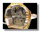
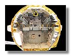
The completed cockpit of Lunar Module 5 is shown on figures 19.
|
|
|
|
|
|
|
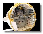
1 : Forward section cockpit - December 2008 |
2 : LM instrument panels - October 2008 |
3a, b, c, d : Making of panels 1, 2 & 3 - January 2009 |
4a : Making of panels 11 & 16 - January 2009 |
|||
|
|
|
|
|
|
|
4b, c, d, e, f, g, h : Making of panels 11 & 16 - January 2009 |
||||||
|
|
|
|
|
|
|
4i, j : Making of panels 11 & 16 - January 2009 |
5a, b, c, d, e : Windows detailling - January - February 2009 |
|||||
|
|
|
|
|
|
|
5f, g, h : Windows detailling - January - February 2009 |
6a, b, c, d : Alignment Optical Telescope - February 2009 |
|||||
|
|
|
|
|
|
|
6e : Alignment Optical Telescope - February 2009 |
7a, b, c, d, e, f : Roof padding - February - March 2009 |
|||||
|
|
|
|
|
|
|
7g, h : Roof padding - March 2009 |
8a, b, c : Panels 8 and 10 - March 2008 |
9a, b : Panels 12 and 14 - March 2008 |
||||
|
|
|
|
|
|
|
10a, b : Rough shape for the main hatch - April 2009 |
11a, b, c : Armrests - April 2009 |
12a, b : Panels 4, 5 and 6 - April 2009 |
||||
|
|
|
|
|
|
|
12c, d : Panels 4, 5 and 6 - April 2009 |
13a, b : Hand controllers - April 2009 |
14a, b : Final assembly of panels 4,5 & 6, armrests and hand controllers - April 2009 |
15a : Forward hatch section - April 2009 |
|||
|
|
|
|
|
|
|
15b, c, d, e, f, g, h : Forward hatch section - May 2009 |
||||||
|
|
|
|
|
|
|
15i : Forward hatch section - May 2009 |
16a, b : Floor - May 2009 |
17a, b, c : Right hand stowage - May 2009 |
18a : Left hand stowage - May 2009 |
|||
|
|
|
|
|
|
|
|
18b : Left hand stowage - May 2009 |
|
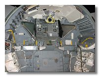
19a, b, c : Completed lunar module cockpit - May 2009 |
|
||
Photographs and blueprints by Vincent Meens, January - May 2009
Front page - Ascent stage mid-section structure - Back-section structure - Back-section details - Mid-section cabin - Mid-section details - Front-section structure
Forward-section cockpit - Forward section details - Completed ascent stage - Descent stage - Moon base - Completed model