Front page - Ascent stage mid-section structure - Back-section structure - Back-section details - Mid-section cabin - Mid-section details - Front-section structure
Forward-section cockpit - Forward section details - Completed ascent stage - Descent stage - Moon base - Completed model
The Ascent Stage Forward-Section
I started building the forward-section-structure prior to complete the mid-section and in particular putting all details such as antennas. The reason for this was simple, since I wanted to be able to remove the front section from the mid-section in order to show the interior of LM-5, it would have been very difficult to work on this connection without breaking or at least endangering the integrity of all small details on the mid-section.
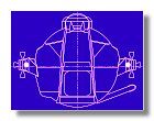
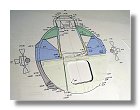
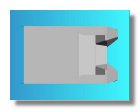
I first started to work on the blueprint for the front-section (see figure 1), drawing the front-section of the ascent stage was quite difficult compare to the two other sections, primarily because of its shape and secondly because of making sure I had a good representation of the cockpit whose shape was much more complicated than the mid-section cabin. A special thanks here to Rafael Finter from Germany who found a few mistakes in the blueprint and helped me to correct them.
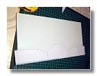
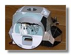
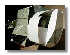
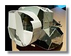
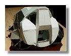
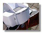
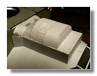
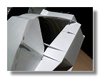
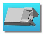
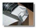
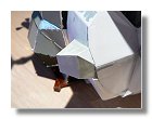
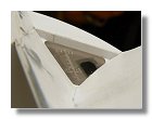
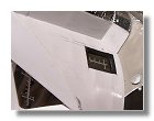
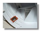
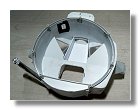
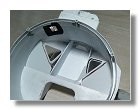
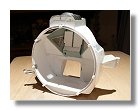
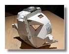
I then started to cut styren using a pattern (see various details drawing), the shape of the cylindrical cabin was made by bending the 0.4 mm styren sheet and using styren arch as stiffeners. Construction of the hatch wall and cabin floor also helped to make the part more rigid. Styren rods were used to establish the connection between the front and the mid-sections of the LM-5 ascent stage (see figures 2).
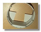
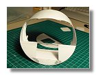
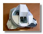
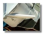
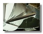
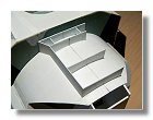
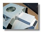
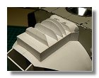
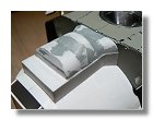
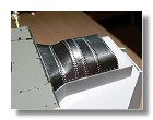
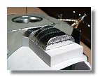
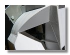
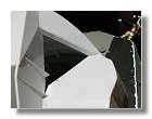
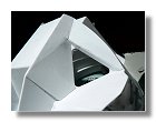
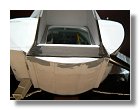
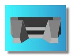
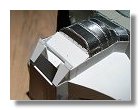
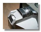
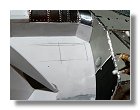
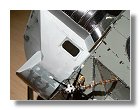
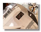
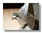
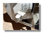
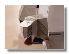
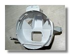
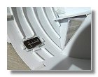
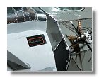
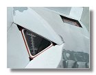
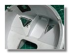
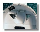
Although the cabin is cylindrical there are two kinds of bulges on either sides of the cabin through which cables and fuel feed lines for the RCS are located. Construction of these bulges are documented in figures 3. I then built the external bar of the main fuel tank support assembly, I covered the bar with adhesive bright aluminium paper prior to install the interface between the bar and the mid-section made up of wrinkled aluminium paper (that configuration seems only valid for LM-5 and is different for further LMs), the process is shown on figures 4. I continued with the contruction of the coffin which housed the periscope and the rendez-vous radar assembly, that was the last part I needed to start building before detailling the mid-section of the ascent stage (see figures 5), I started the coffin in April and only finished it in October since in the mean time I completed the mid-section details. Once the coffin structure was finished I applied the aluminium shiny panels (they were chromic acid anodized panels on further LMs). Since those panels are not straight in any way I had to make a pattern for each panel using adhesive tape that I applied on adhesive aluminiun paper to cut each panel with the correct shape. I then used a pounce wheel to make the rivets shown in figures 5f and 5g.
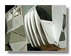
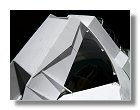
The next task was to install the panels around the main windows, shaping the LM front section with its two eyes as shown in figures 6 and building the front porch (figure 7). Building the panels around the Forward Inertial Measurement Unit (FIMU) proved more difficult as the part has many facets. The 2D blueprint was not sufficient to get a clear picture of the part so I decided to create a 3D picture shown in figures 8 using the free Alibre Express software. The making of the part itself is shown in figures 9.
For the overhead rendezvous window I had to cut the outer left overhead panel and build a recess since the window is not aligned with the outer panel (figures 10). The last part of the external structure was building the forward RCS making sure these being perfectly aligned with the aft RCS (figures 11).
Before starting to build the internal structure of the forward section I had to make the windows since they consist of at least two separate layers that are fixed between the outer and inner walls of the section. The CDR window and the rendezvous window each have markings, for the CDR window the reticles are used to visualize the landing target, the numbers being correlated with the numbers given by the onboard computer. For the rendezvous window the markings help to align the LM with the CM docking target. At first I thought about creating decals for these markings, unfortunatly I realize the markings were white which was a color not possible to print with an inkjet printer on transparent decals. I then decided to engrave the marking using a precision knife. When seen with magnifying glasses you see the marking are hand made, however this is not visible with the naked eye (see figures 12). I then made the cylindrical inner wall of the cockpit and at the same time finished the rendezvous window by inserting the rubber joint and the inner glass layer (see figures 13).
I then put the rest of the panels around the main windows. Again, as shown in the process in figures 14 the windows are composed of two layers of clear plastics with a rubber joint in-between made out of styren with an ochre paint. When I finaly glued the first elements of the cockpit display, the forward section of LM-5 was completed (figures 15).
|
|
|
|
|
|
|
1 : Front-section blueprint |
2a, b, c, d, e, f : Building the main forward-section structure - March 2008 |
|||||
|
|
|
|
|
|
|
3a, b, c, d : Building the cabin bulges - March - April 2008 |
4a, b, c : Main bar of the fuel tank support assembly - April 2008 |
|||||
|
|
|
|
|
|
|
5a, b, c, d, e, f, g : Construction of the coffin - April - November 2008 |
||||||
|
|
|
|
|
|
|
6a, b, c, d, e, f : Panels around the main windows - November 2008 |
7 : Front porch : November 2008 |
|||||
|
|
|
|
|
|
|
8a, b, c : FIMU 3D rendering - November 2008 |
9a, b, c : Forward Inertial Measurement Unit - November 2008 |
10a : Overhead rendezvous window - November 2008 |
||||
|
|
|
|
|
|
|
10b, c, d : Overhead rendezvous window - November 2008 |
11a, b, c, d : Forward RCS - November - December 2008 |
|||||
|
|
|
|
|
|
|
12a, b : LM windows : December 2008 |
13a, b, c, d, e : Inner cylindrical wall : December 2008 |
|||||
|
|
|
|
|
|
|
14a, b, c, d, e : Panels around windows - December 2008 |
15a, b : Completed forward section structure - December 2008 |
|||||
Photographs and blueprints by Vincent Meens, March - December 2008
Front page - Ascent stage mid-section structure - Back-section structure - Back-section details - Mid-section cabin - Mid-section details - Front-section structure
Forward-section cockpit - Forward section details - Completed ascent stage - Descent stage - Moon base - Completed model