Front page - Ascent stage mid-section structure - Back-section structure - Back-section details - Mid-section cabin - Mid-section details - Front-section structure
Forward-section cockpit - Forward section details - Completed ascent stage - Descent stage - Moon base - Completed model
The Ascent Stage Mid-Section details
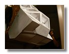
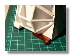
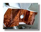
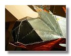
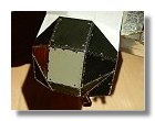
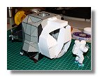
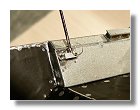
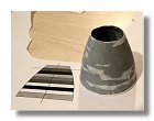
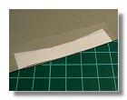
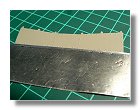
The details on the mid-section started with the application of the 5 mil aluminized kapton (figures 2), however before fixing it, it was necessary to put styren panels on the mesh structure, the idea being that anytime I wanted to put a new panel like anodized aluminium panel or kapton, I completed the styren panels around that particular one. Actually since the thermal panels are quite thin it was not convenient to put them on the mesh structure which is the reason why I had to implement the styren panels.
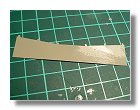
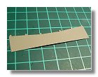
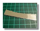
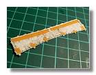
Application of the 5 mil kapton was not very easy, this was quite a strong material not easy to fold. I first made a paper pattern (easier to fold) which I then used to cut the kapton foil. I then had to crinkle it and make the fold lines before applying it on the bottom part of the mid-section.
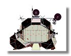
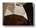
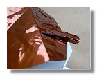
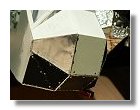
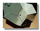
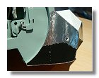
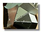
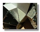
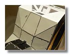
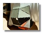
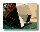
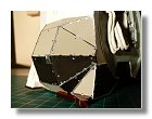
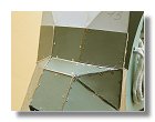
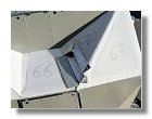
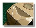
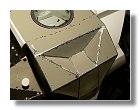
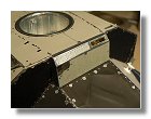
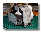
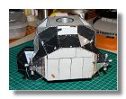
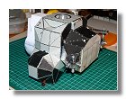
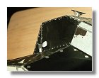
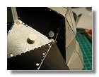
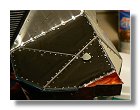
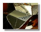
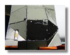
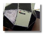
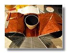
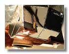
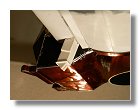
I then started to apply the various protection panels. There are bascally three types of panels, clad aluminium 20024-T3 either with a black pyromark paint or half shiny and bare aluminium 5056-H191, chromic acid anodized (light grey with a touch of green). For the black pyromark I had some left-over from LM-13 which I used for this model, I used adhesive aluminium paper for the half shiny clad aluminium panels and finally I painted paper with Humbrol 40 to give the appearance of the chromic acid anodized panels. The whole process can be seen in figures 3 for the left side, figures 4 for the right side and figures 5 for the top side. You can note that LM-5 presented pattern chararcteristics that are unique to this vehicle; for instance in figure 4g the upper edge of panel 116 (the black panel) is black where it is aluminium for all other lunar LM, an other example is the umbilical on panels 113 and 114 (the aluminium panels) which is bright aluminium on LM-5 and bright gold for the further LMs.
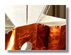
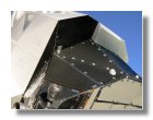
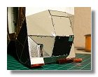
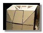
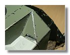
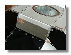
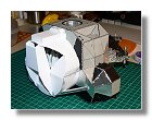
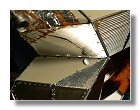
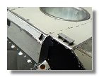
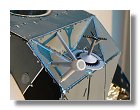
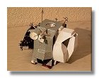
The last part of panel covering was for the top of the mid-section. Here again there are some specifics for LM-5. Althought he pattern is almost identical for all LMs the use of kapton tape is quite different and specific for each LM. LM-5 had a particular silver tape pattern that I tried to reproduce (see figures 5). Panel 156 which hosts the EVA antenna was the last work on the panel aplication for the mid-section (see figures 6). The mid-section completely covered with all its panel can be seen in figures 7.
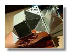
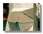
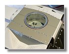
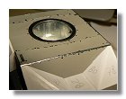
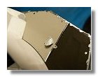
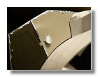
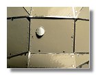
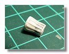
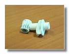
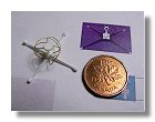
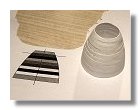
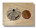
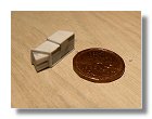
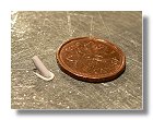
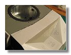
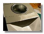
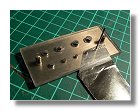
The first detail to be built was the docking target (see figures 8). This was made out of styren except for the cone at the base of the target wich was made from paper. In order to have a nice rendering I simply printed the pattern found in the detail blueprint on gloss paper using a laser printer. By means of double-sided adhesive tape I put each pattern onto a 0.5 mm styren part (except for the cone whch remained only in paper. I then made all the vents, the making of each being identical to the vents on the back section (see figures 11 of that section). Pictures of each vent are seen in figures 9.
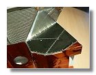
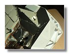
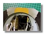
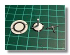
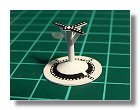
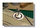
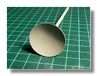
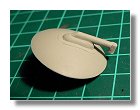
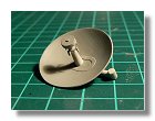
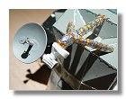
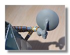
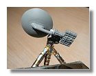
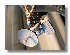
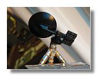
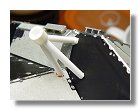
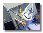
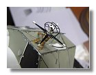
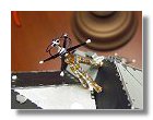
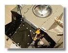
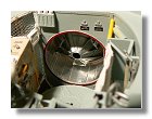
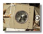
The next step was the construction of the S-Band antenna. This is probably the most complicated part of the mid-section external detailing. This is a parabolic antenna so I had to thermoform it using 0.4 mm styren. For the correct thickness of the antenna I used a medium light bulb and simply heated the styren sheet over the bulb. I then cut the correct diameter (2.8 mm). Dimensions of the S-Band antenna can be found in the detail blueprint. Contruction of the antenna is shown in figures 10. The orientation of the S-Band antenna is discussed in the Elevation and Azimuth of the LM S-band antenna section. Note that the electronic package (the box at the bottom of the S-band motor) makes an angle of about 30° with the S-band motor; it is interesting to note that in the case of Apollo 11, the S-band dish was quasi aligned with the electronics box making it easier to orient on the model.
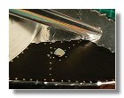
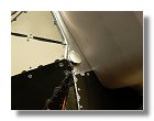
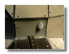
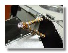
Small items were then added such as the Ascent Power System (APS) fuel drains (figure 11), the rendez-vous green and red lights (figures 12) and the primary and secondary H20 boilers (figure 13).
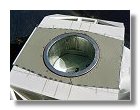
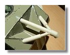
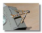
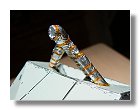
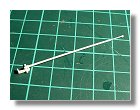
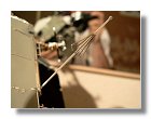
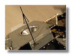
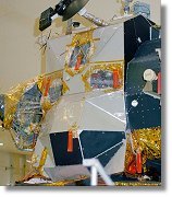
The final details to be added were the VHF antennas (figures 14), the EVA antenna (figures 15), the ascent engine bell (figures 16), the docking cone (figures 17) and the umbilicals (figures 18). Note that the EVA antenna was built right after the VHF antenna in order to adjust the EVA antenna restraint onto the aft VHF antenna truss when the EVA antenna is folded. The completed mid-section of the LM ascent stage is shown in figure 19.
|
|
|
|
|
|
|
1 : Detail blueprint - June 2009 |
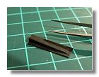
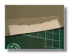
2a, b, c, d, e, f : Application of 5 mil aluminized Kapton - November 2007 |
|||||
|
|
|
|
|
|
|
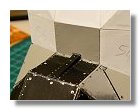
3a, b, c, d, e, f, g : Mid-section coating - Left side : November 2007 - January 2008 |
||||||
|
|
|
|
|
|
|
3h, i, j, k, l, m, n : Mid-section coating - Left side : January - February 2008 |
||||||
|
|
|
|
|
|
|
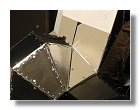
4a, b, c, d, e, f, g : Mid-section coating - Right side : February - April 2008 |
||||||
|
|
|
|
|
|
|
4h, i : Mid-section coating - Right side - April 2008 |
5a, b, c, d, e : Top coating - April - May 2008 |
|||||
|
|
|
|
|
|
|
5f, g, h : Top coating - May - June 2008 |
6a, b : Panel 156 - June 2008 |
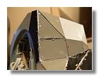
7a, b : Complete application of panels - June 2008 |
||||
|
|
|
|
|
|
|
7c, d, e : Complete application of panels - June 2008 |
8a, b, c : Docking target - June 2008 |
9a : Vents - June 2008 |
||||
|
|
|
|
|
|
|
9b, c, d, e, f, g, h : Vents - June 2008 |
||||||
|
|
|
|
|
|
|
9i, j : Vents - June 2008 |
10a, b, c, d, e : S-Band antenna - June - September 2008 |
|||||
|
|
|
|
|
|
|
10f, g, h, i, j, k, l : S-Band antenna - September 2008 |
||||||
|
|
|
|
|
|
|
10m : S-Band antenna - September 2008 |
11 : DSP fuel drains - September 2008 |
12a, b : Rendez-vous lights - September 2008 |
13 : Secondary H2O boilers - September 2008 |
14a, b : VHF antennas - September 2008 |
||
|
|
|
|
|
|
|
14c, d, e, f, g : VHF antennas - September 2008 |
15a, b : EVA antenna - September - October 2008 |
|||||
|
|
|
|
|
|
|
15c, d, e : EVA antenna - October 2008 |
16a, b, c : Ascent engine bell - October 2008 |
17a : Docking cone - October 2008 |
||||
|
|
|
|
|
|
|
17b, c : Docking cone - October 2008 |
18a, b, c, d : Umbilicals - October 2008 |
19 : Completed mid-section - October 2008 |
||||
Photographs and blueprints by Vincent Meens, November 2007 - October 2008
How to Make the Panels
Making each panel was a long process, not really difficult but requiring patience and time. As the previous section describe the general making of the model, this section describes the precise steps required to make a panel. The example concerns panels 47 to 49 which are anodized aluminium 5056-H191 panels. In this case the process was a bit more difficult since I had to produce the material used to make the panels (painted paper with Humbrol 40). For the other panels I already had black aluminium sheets and adhesive bright aluminium, so the process was a bit quicker but the steps remained very similar.
|
|
|
|
|
|
|
|
|
|
|
|
|
|
Elevation and Azimuth of the LM S-band antenna
Once on the surface of the Moon, communication with the Earth depended on the S-band antenna (around 2 GHz). The LM had three S-band antennas, two omni-directional antennas on the aft and forward sections of the ascent stage and a high gain steerable antenna on the mid-section of the ascent stage. If we want to accurately depict an Apollo landing site, it is important to orient the steerable S-band antenna correctly. The following article describes how to calculate the orientation of the LM S-band antenna taking into consideration the Earth, Moon and LM geometry.
Front page - Ascent stage mid-section structure - Back-section structure - Back-section details - Mid-section cabin - Mid-section details - Front-section structure
Forward-section cockpit - Forward section details - Completed ascent stage - Descent stage - Moon base - Completed model