Front page - Ascent stage mid-section structure - Back-section structure - Back-section details - Mid-section cabin - Mid-section details - Front-section structure
Forward-section cockpit - Forward section details - Completed ascent stage - Descent stage - Moon base - Completed model
The Ascent Stage Back-Section
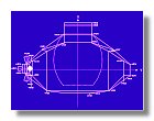
The back-section of the ascent stage contains helium tanks, oxygen supplies, communication systems and batteries as well as two of the four RCS (Reaction Control System) quads. For the model, this section needed to be removable in order to show the inside cockpit of the lunar module. Before cutting any styren I, as for the mid-section, had to draw a blueprint. Values in this blueprint are in cm for a 1/24 model (Figure 1).
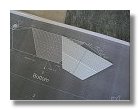
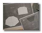
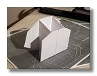
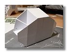
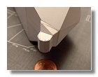
The first thing to do was to build the bottom plate of the back-section. This was the only part of that section not covered by subsequent plate, at this stage it was the only detail to build. Process is shown on figures 2. Note that on figure 2b I started to cut the front and back sections that were assembled later-on to form the first basic structure (figure 3).
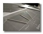
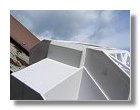
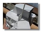
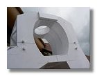
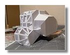
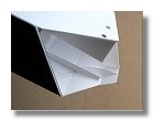
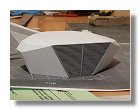
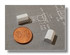
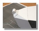
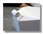
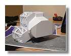
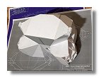
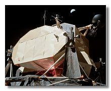
I then had to find a way to make the back section removable. For this I built on the mid-section the compartment containing the connections to the EVA and VHF antennas, this was used to secure the upper part of the back-section. I then drilled four holes on the bottom parts of the mid and back-sections. Rods were glued on the mid-section to fit perfectly with the holes on the back section. This way it was easy to install or remove the back- section. Figures 4 shows the whole process. The various plates were then installed as shown in figures 5, note that I had to use inside supports as shown in figure 5d for the RCS plate which is not directly connected to either the main internal or external faces of figure 3. The final thing to do was building the two RCS quads (figures 6), the small rods visible on figure 6d will be used later-on as guides to install the RCS thrusters. The final ascent back structure is shown on figures 7.
|
|
|
|
|
|
|
1 : Back-section blueprint - February 2007 |
2a, b, c : Building the bottom plate of the back-section - February 2007 |
3 : First assembly of the back section
structure - |
4a, b : Building connection between mid and back-sections - February 2007 |
|||
|
|
|
|
|
|
|
4c : Building connection between mid and back-sections - February 2007 |
5a, b, c, d, e : Assembly of the back-section plates - February 2007 |
6a : Building RCS quads- |
||||
|
|
|
|
|
|
|
|
6b, c, d : Building RCS quads - February 2007 |
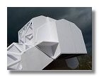
7a, b : Completed back & mid-sections structure - |
|
|||
Photographs and blueprints by Vincent Meens, February 2007
Front page - Ascent stage mid-section structure - Back-section structure - Back-section details - Mid-section cabin - Mid-section details - Front-section structure
Forward-section cockpit - Forward section details - Completed ascent stage - Descent stage - Moon base - Completed model