Front page - Ascent stage mid-section structure - Back-section structure - Back-section details - Mid-section cabin - Mid-section details - Front-section structure
Forward-section cockpit - Forward section details - Completed ascent stage - Descent stage - Moon base - Completed model
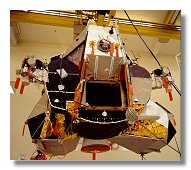
The Ascent Stage Forward-Section Details
This was the final step in completing the ascent stage. I knew that I could not complete this model before Apollo 11 40th anniversary but maybe there was a chance to complete the ascent stage and show it during a special day at the Cité de l'Espace space museum in Toulouse. If I wanted to do that I had to complete the interior by the end of May. I actually completed it by mid-May and started to work on detailling the forward structure.
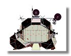
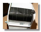
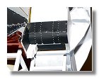
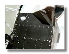
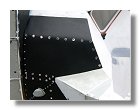
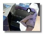
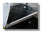
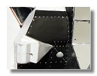
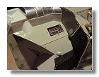
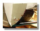
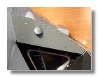
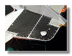
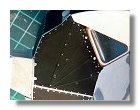
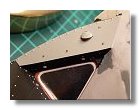
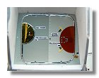
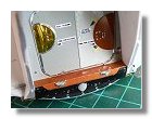
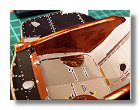
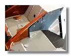
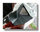
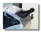
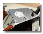
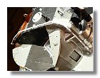
The work here was very similar to the back-section and mid-section detailling, i.e. to affix various panels of different colors while detaillling them with the proper rivets. The detail blueprint in figure 1 was a very important asset in ensuring the authenticity of each panel. I started by putting all panels around the forward section as seen in figures 2 and then around the CDR window (figures 3) and the LMP window (figures 4).
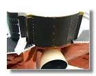
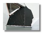
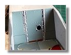
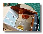
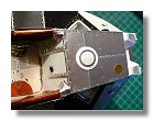
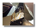
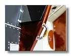
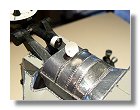
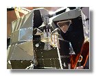
Before putting the last panels around the CDR and LMP windows (panels 31 and 32), I first had to complete the panels around the hatch (figures 5), the reason being that panels 31 and 32 (black pyromark) are partly put over panels 33 and 34 made of 5 mil aluminized kapton. Modelling the 5 mil kapton proved to be a difficult task as the material is quite rigid. The only way to fix it on the model was by using super glue. Once this was done I finally completed the panels around the two LM windows (figures 6). I then completed the panels around the cockpit (figures 7) and the RCS (figures 8) before starting the details.
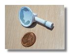
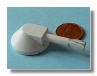
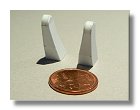
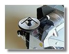
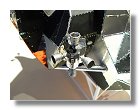
The major detail on the forward section was the rendezvous radar antenna. However since most of it was covered with black pyromark, it was easier to build than the S-band antenna. I made sure that the antenna was pointing upward as it was the case on the Moon for Apollo 11 (see figures 9). Finally I set up small details like the hatch handle (figure 10), the AOT (figure 11), the rendez-vous lights and the omnidirectional S-band antenna (figure 12), the EVA handrail (figure 13) and the RCS thrusters (figures 14).
|
|
|
|
|
|
|
1 : Details blueprint - June 2009 |
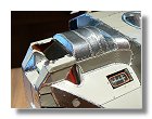
2a, b, c, d, e, f : Coating around the forward section - May 2009 |
|||||
|
|
|
|
|
|
|
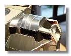
2g, h, i : Coating around the forward section - May 2009 |
3a, b, c : Coating around the CDR window - June 2009 |
4a : Coating around the LMP window - June 2009 |
||||
|
|
|
|
|
|
|
4b, c : Coating around the LMP window - June 2009 |
5a, b, c, d, e : Coating around the Hatch - June 2009 |
|||||
|
|
|
|
|
|
|
6a, b, c : Final coating around the windows - June 2009 |
7a, b : Final coating around the coffin - June 2009 |
8a, b : Coating around the RCS - June 2009 |
||||
|
|
|
|
|
|
|
8c : Coating around the RCS - June 2009 |
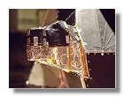
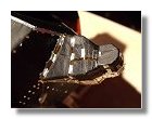
9a, b, c, d, e : Rendezvous radar antenna - June 2009 |
10 : Hatch handle - June 2009 |
||||
|
|
|
|
|
|
|
|
11 : AOT - July 2009 |
12 : Rendezvous lights and S-band antenna - July 2009 |
13 : EVA handrail- July 2009 |
14 : RCS - July 2009 |
|
|
Photographs and blueprints by Vincent Meens, May - July 2009
Front page - Ascent stage mid-section structure - Back-section structure - Back-section details - Mid-section cabin - Mid-section details - Front-section structure
Forward-section cockpit - Forward section details - Completed ascent stage - Descent stage - Moon base - Completed model