Front page - Ascent stage mid-section structure - Back-section structure - Back-section details - Mid-section cabin - Mid-section details - Front-section structure
Forward-section cockpit - Forward section details - Completed ascent stage - Descent stage - Moon base - Completed model
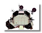
The Ascent Stage Back-Section Details
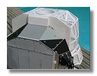
The ascent stage is covered by thermal covering panels made out of either anodized aluminium, flat black, dull silver or wringled aluminium foils. These foils are connected to the structure by rivets. You can see also some dark gold adhesive amber kapton tape in several places. Considering the size of the model I wanted to show it as close as possible to the real LM. I used as a reference the very good drawings from David Weeks and Paul Fjeld, I resized them to approximatively 1/24 and added details of the rivets (see figure 1), I also included in these drawing the shingling pattern (indicated by arrows) and the actual panel numbers.
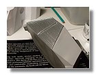
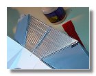
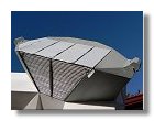
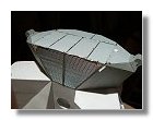
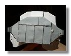
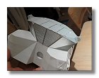
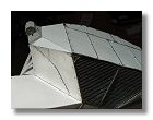
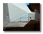
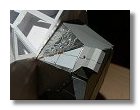
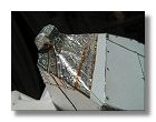
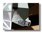
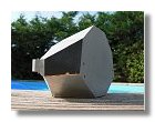
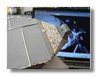
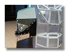
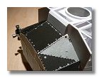
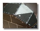
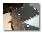
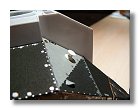
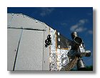
I started by applying chrome paint onto the grid plate (figure 2) and some wringled aluminium foil onto this plate (figure 3). Figure 4 shows the process of applying the thermal covering onto the back side of this section. For this I used some metalized grey paper used for scrapbooking. I then applied stripes of adhesive chrome paper (about 0.5 mm wide) around the grey scrapbooking paper. The adhesive chrome paper is called Solartrim, it is very thin and easy to apply (see www.solarfilm.co.uk) and mainly used for remote aircraft models. The rivets are cut into adhesive alumimium paper using a good pair of binolular considering its small size. Each plate is then applied onto the structure using double sided adhesive tape. The adhesive tape is applied only in the area of the rivets making the thermal covering unperfectly joined as for the real LM.
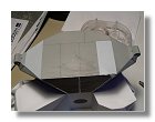
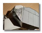
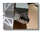
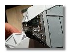
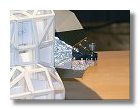
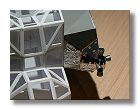
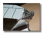
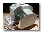
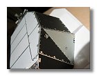
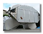
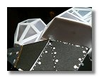
I then covered the rest of the back section, starting with the bottom plates, for this I used dull aluminium paper. The rivets are either 1 mm diameter bright adhesive aluminium paper or simply a dot written with a permament silver marker (figures 5). I followed by adding the thermal covering around Quad 2 (figures 6). Note that the covering for both quads is different. It is also important to realize that the thermal covering for LM-5 is realy unique, in particular the wringled aluminium paper found around both quads is only valid for LM-5. Starting with Apollo 12 the RCS quads were covered with flat black layers only. Since Apollo11 had only one EVA, they aren't so many photos clearly showing detailed views of the RCS, a special thank here to some some individuals like Karl Dodenhoff, Jim Key, Paul Fjeld and John Ortmann who provided me with very detailled views of this area of LM-5.
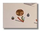
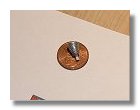
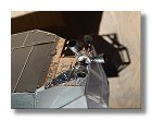
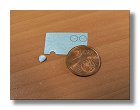
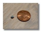
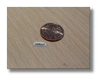
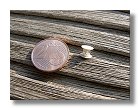
Before continuing on covering the back section with thermal blankets I built the RCS thrusters for Quad 2 (drawings are available here). Since I had 16 thrusters to build in total, building 4 of them each time I completed an RCS quad made the process less boring. As depicted in figures 7, I built the thrusters out of paper, in figure 7a and 7b the thrusters are depicted against a 2 Euro cent for sizing; a 2 Euro cent has the same dimension as a 1 US Dollar cent. Considering the small size of each one I decided paper was the easiest material to use. Each nozzle was made out of several cones of paper and covered with putty to hide any imperfection. The cooling tubes are either a small wire or strips of adhesive aluminium paper. The complete truster is than painted with Revell 91 and put into place.
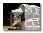
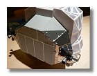
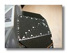
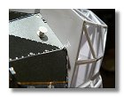
I then put thermal coverings around RCS Quad 3 (figures 8) and completed the thrusters (figure 9). Before putting the last details I had to apply the thermal blankets on the top part of the back section as shown in figures 10. The large rivets are 1.5 mm aluminium circles, le middle size, 1 mm aluminium circle and and the small ones are made by simply writing a dot with a silver pen.
I then started to build the small details beginning with the aft panel vents (drawing available here). The covering of the vent was done using silver scrapbooking paper on which I printed the pattern. Having designed the pattern on a computer allowed to build the same vents for all the ascent stage. The covering was then glued onto the half cut circle shown on figure 11b (diameter 3.5 mm), this allowed to precisely cut the part used to fix the covering onto the panel. The whole process is shown in figures 11. Please note that one of the vent is looking backward and the other one forward. I have noticed as a common mistake to have either both vents backward or forward.
Figures 12 show an other detail on the aft panels of the back section, this particular detail is never mentioned in the LM litterature. I looked for instance in the 804 pages of the LM handbook and found nothing about it. Although it looks like some kind of antenna, nothing is mentionned in the communication chapter about such a system. An other thing is that when you compare this photo of LM-5 being built and this photo of LM-5 on the Moon it is interesting to note that this part was added after the panel was installed. I even wonder if there was a connection with some system inside the back section. If by chance some former LM constructor read these lines I would be interested to know about it. You can drop me a mail at vincent.meens@orange.fr.
Figure 13 shows the white docking light, the red and green docking light being on the mid-section of the ascent stage.
I then built the suit circuit steam vent deflector (figures 14), this was also one mystery part on the LM, however thanks to knowledgable people on the space-modelers yahoo group I got an explanation of the purpose of this part. Karl Dodenhoff and Paul Fjeld need to be thanked here. The central tube is made out of a 3.5 mm transparent plastic tube and the two caps are 6 mm diameter styren circles.
The next step of building details for the back section was the S-band omnidirectional antenna (drawing available here at 1/2.4 scale, to be printed at 10%). This antenna is used in the communication subsystem for telemetry between the LM and the MSFC. Because it is omnidirectional telemetry signal can be received whatever the position of the LM is. However since the LM itself can obstruct communication with the Earth an other identical S-band omnidirectional antenna is situated on the front part of the ascent stage above the main hatch. This disposition allows one of the two antennas to be always visible from the Earth. The S-band signal has a circular polarization, this is the reason why the antenna consists of two helix. All the 1/48 models show this antenna as a cone but at 1/24 I really wanted to display the two helix. However even at this scale this was a small part to build and not an easy one. Again I used paper to print a pattern for the helix but I had to design the pattern at 1/2.4 and print it at 10% scale. The base of the antenna is styren as well as the central mast. The helix was made out of paper reinforced later on by varnishing it and even coating it with liquid superglue. It was finally painted in black and installed on the aft panel of the back section (see figures 15).
The final step was building the Ascent Helium Overboard Vent tubes. This particular detail was pointed out to me by Paul Fjeld as I have to admit I completely missed it on pictures. On the assembly pictures of LM-5 and others it is clearly visible, this vent tube is further in from the steam vent right at the intersection of the top of the equipment bay and the mid-section. On pictures of the LM on the Moon it is covered with some kind of plastic bag (see AS11-40-5922HR). There were two vents to build, one on each side of the back section (see figures 16).
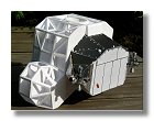
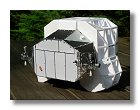
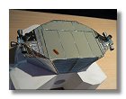
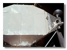
The finished back section is shown in figures 17. I thought the back section was finished with figures 17a and b but that was before I went under AMS and I realized that the anodized aluminium panels didn't have the right color (I was fortunate to get a small piece of a real LM panel from Paul Fjeld). After several trials I found that using very fine styren sheet (0.125 mm) and painting it with Humbrol 40 gave quite an honest result. You can see the difference in figure 17c. Of course I had to remove the old panels and replace them with the new ones, that was a bit painfull when you finish a part of a model but much better to to this at this stage than later-on when the model is almost finished.
|
|
|
|
|
|
|
1 : Details blueprint - June 2009 |
2 : Grid plate painting - March 2007 |
3 : Aluminium foil application : March 2007 |
4a, b, c, d : Back side anodized plate application - March 2007 |
|||
|
|
|
|
|
|
|
5a, b: Dull aluminium plate application - March 2007 |
6a, b, c, d, e: Thermal covering around RCS Quad 2 - April 2007 |
|||||
|
|
|
|
|
|
|
6f, g : Thermal covering around RCS Quad 2 - April 2007 |
7a, b, c, d : RCS thrusters for Quad 2 - April 2007 |
8a : Thermal covering around RCS Quad 3 - April 2007 |
||||
|
|
|
|
|
|
|
8b, c, d, e : Thermal covering around RCS Quad 3 - April - May 2007 |
9 : Completed RCS Quad 3 - May 2007 |
10a, b : Top thermal covering - May 2007 |
||||
|
|
|
|
|
|
|
10c, d : Top thermal covering - May 2007 |
11 a, b, c, d, e : Aft panel vents - May 2007 |
|||||
|
|
|
|
|
|
|
12a, b : Aft panel detail - June 2007 |
13 : White docking light - June 2007 |
14a, b : Suit circuit steam vent deflector - June 2007 |
15a, b : S-band omnidirectional antenna - June 2007 |
|||
|
|
|
|
|
|
|
|
16a, b :Right hand ascent helium overboard vent tube - June 2007 |
17a, b, c : Completed LM-5 ascent stage back section - June 2007 |
|
|||
Photographs and blueprints by Vincent Meens, March - June 2007
Front page - Ascent stage mid-section structure - Back-section structure - Back-section details - Mid-section cabin - Mid-section details - Front-section structure
Forward-section cockpit - Forward section details - Completed ascent stage - Descent stage - Moon base - Completed model