Front page - Wheels - Chassis - Assembling - Body - Details - Cameras - Antennas - Laser reflector, instruments - RTG - Lid - Odometer & Penetrometer - Moon base - Completed Model
The Body
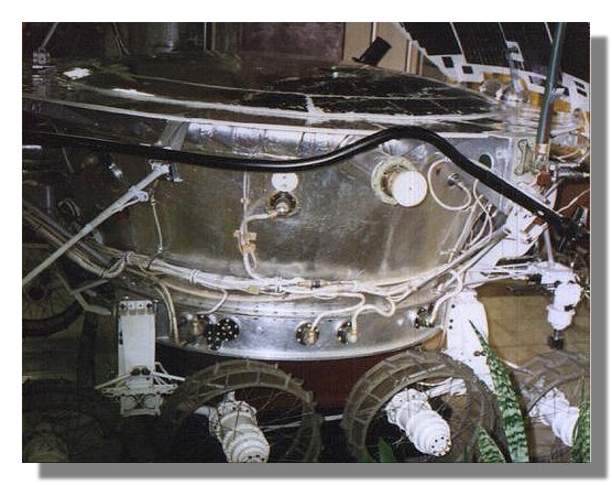
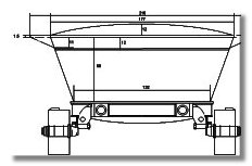 The main body of the lunokhod supports the instrument and power systems of the vehicle. Its particular shape was designed to keep all the
systems at the right temperature either during the lunar day or the lunar night. During the day power was supplied thanks to solar cells
located on top of the main body as well as on the lid. During the night the lid was closed and power was supplied through an RTG
(Radio-isotopic Thermal Generator). Figure 1 shows the basic dimensions of the main body of the lunokhod. As for the other parts of this
model the blueprint is provided as a pdf file.
The main body of the lunokhod supports the instrument and power systems of the vehicle. Its particular shape was designed to keep all the
systems at the right temperature either during the lunar day or the lunar night. During the day power was supplied thanks to solar cells
located on top of the main body as well as on the lid. During the night the lid was closed and power was supplied through an RTG
(Radio-isotopic Thermal Generator). Figure 1 shows the basic dimensions of the main body of the lunokhod. As for the other parts of this
model the blueprint is provided as a pdf file.
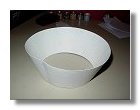
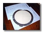
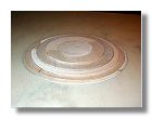
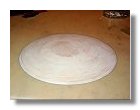
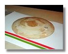
The first thing to do was to model the cone of the body; this was done in strong cardboard using the technique explained in the tips and tricks section to develop a cone. The values of L, l and a are as follows : L = 285 mm, l = 213 mm and a = 111.7895°. The completed cone is shown in figure 2.
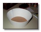
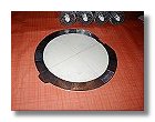
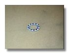
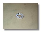
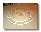
In order to strengthen the cone several cardboard circles are placed within the cone as shown on figures 3a and 3b. From the bottom of the cone to the top the variation between each circle is an increase of 1 cm of the diameter. The imperfections of the cone are then masked using a plaster coating and the cone is sanded and varnished several times. A band of slim cardboard is also glued 12 mm from the top as shown in figure 3b in conformity with the blueprint.
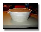
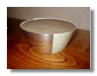
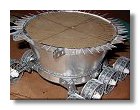
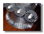
Instead of painting the cone I have used self-adhesive aluminium paper which is placed all around the cone as figure 4 shows, this give the shiny aluminium appearance of the lunokhod. Once this is
completed the cone is then glued on top of the chassis as shown is figure 5.
|
|
|
|
|
2 : Cutting the cone - December 2002 |
3a, b : strengthening the cone - December 2002 |
4 : Aluminium coating - January 2003 |
5 : The cone is glued onto the chassis - January 2003 |
|
Photographs and blueprints by Vincent Meens, December 2002 - January 2003
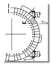
 The next step is to install the support parts all around the main body and directly supporting the outer part of the lid. Although it may seem that all
support parts are equally spaced all around the main body, it appears that some are missing to allow the installation of various sensors, cameras
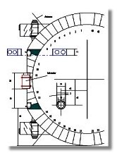
etc... Two blueprints have then been produced, one for the front part of the lunokhod (where the main TV cameras are) and one for the back
part (where the RTG is). Two blueprints were necessary to keep the dimension of the 1/10 scale model on A4 paper sheets. Figure 6 and figure
7 are the two blueprints detailling the positionning of the support part as well as other details.
The next step is to install the support parts all around the main body and directly supporting the outer part of the lid. Although it may seem that all
support parts are equally spaced all around the main body, it appears that some are missing to allow the installation of various sensors, cameras
etc... Two blueprints have then been produced, one for the front part of the lunokhod (where the main TV cameras are) and one for the back
part (where the RTG is). Two blueprints were necessary to keep the dimension of the 1/10 scale model on A4 paper sheets. Figure 6 and figure
7 are the two blueprints detailling the positionning of the support part as well as other details.
The angle betwen each support part is 6.43°, this means that the lid could accomodate up to 56 support parts. Since there are holes in the positionning of these parts, the total number of support parts is 46. All of them have been numbered as shown on figure 6 and figure 7, this will be helpful later on when we will build the various details present on the main body.
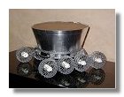
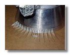
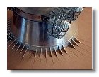
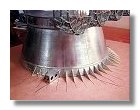
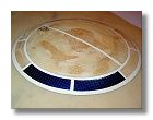
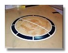
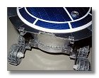
Based on the blueprint I have produced a precise template figuring the positionning of the support parts on a 90° quadrant. I started by building support parts 33 to 46 corresponding to the left front part of the lunokhod as well as one of the special support parts inserted between support part 37 and 39. This particular one will be used later on to build the truss structure for the high gain antenna. Each support part is cut into the same carboard used to shape the main cone of the body, it is then covered with adhesive aluminium paper and pasted onto the body using super glue. This particular part of the work is displayed in figure 8a.
Figure 8b shows the installation of support parts 22 to 32, please note that support part 32 is longer that the other ones to accomodate an extension of the body top. Figure 8c shows the installation of support parts 1 to 11 and figure 8d the installation of support parts 12 to 21, please note the parts with holes that will support the opening mechanism for the lid.
Once all support parts are pasted onto the lunokhod body the bopdy top need to be prepared. The body top is cut within a strong cardboard (thickness of about 1.2 mm) and then covered with aluminium
paper. The top side is covered first as shown in figure 9, the middle of this side is not covered because it will be covered later on by the solar panel. For the top side I have used non adhesive aluminium
paper mainly because it is not as thick as the adhesive one so it is easier to cover the edge of the top side. Figure 10 shows the aluminium coating of the bottom side, in this case adhesice aluminium papare
is used. Finally the top is assembled on the main lunokhod body as shown in figure 11.
|
|
|
|
|
|
|
8a,b,c,d : Installing the support parts - January - February 2003 |
9 : Aluminium coating of the body top (top side) - February 2003 |
10 : Aluminium coating of the body top (bottom side) - February 2003 |
11 : Assembling the body top - February 2003 |
|||
Photographs and blueprints by Vincent Meens, January - February 2003
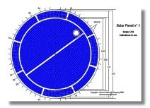 Following the completion of the body, one need to install the solar panel on the body top. The lunokhod has two solar panels, one on the body top and one on the lid.
Figure 12 besides is a blueprint showing the particular pattern of the solar panel. In order for this solar panel to look as close as possible to the original one I have
decided to use blue-colored aluminium paper, the paper is cut in small 3x3 mm rectangles and pasted on the body top according to the pattern shown on the blue
print.
Following the completion of the body, one need to install the solar panel on the body top. The lunokhod has two solar panels, one on the body top and one on the lid.
Figure 12 besides is a blueprint showing the particular pattern of the solar panel. In order for this solar panel to look as close as possible to the original one I have
decided to use blue-colored aluminium paper, the paper is cut in small 3x3 mm rectangles and pasted on the body top according to the pattern shown on the blue
print.
As shown on the blueprints the solar panel has a cupola shape and what appears as an access door is disposed on its top side. This access door is first built using cardboard, balsa wood and needle heads as for the chassis, this is shown on figures 13a and 13b. For the solar panel itself this is done by pasting on top of each other several circles of balsa wood of different diameters as shown on figure 14. Once this is done the solar panel is then sanded (figure 15) and the access door is glued onto the cupola (figure 16).
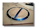
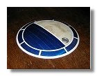
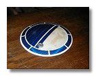
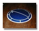
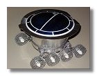
The solar panels edges are first painted onto the cupola using gloss white paint (figure 17). The solar panels themselves are then installed, for this I have used colored aluminium paper that you can find in craft shops. For the peripherical panels, each one is cut into the aluminium paper and, using a cutter, dents are made every 3 mm to reproduce the solar cells pattern (each solar cell is then viewed as a 3x3 mm square. Once this process is done (the dents will not be too strong as to not cut the aluminium paper) double sided adhesive tape is used on the underside of each panel and the panel is then installed on the cupola. For the central panels the same process is used, however I have used several 12 mm bands of aluminium paper, this represents 4 solar cells in the width and about the width of the double sided adhesive paper. All this process is illustrated in figures 18. Once the solar panel is completed it is then assembled onto the body top using wood glue and super glue for the edge of the solar panel. A gloss cote is also applied onto the solar cell to protect them (figure 19).
The last thing to do about this section is to build the attachments to the lid. The basic dimension of these attachments are taken from the blueprint in figure 6. This consists of two cardboard rectangles of
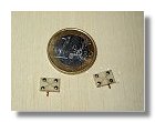
about 6.5 x 9 mm on top of which four needle heads are pasted using super glue. A small copper hook is also glued insided each attachements, this will be used later on to allow the lid to open and close.
Once built the two attachements are varnished before being painted in silver color (Revell 91), note the 1 euro coin on figure 20 as a scale. The two attachements are then glued onto the body top using
super glue (figure 21).
|
|
|
|
|
13a,b : Building the access door on the solar panel - February 2003 |
14 : Assembling the solar panel - February 2003 |
15 : Sanding the solar panel - February 2003 |
16 : Assembling the access door on the solar panel - February 2003 |
|
|
|
|
|
|
17 : Painting the solar panels edges - February 2003 |
18a,b,c,d : Assembling the solar panels - February 2003 |
|||
|
|
|
|
|
18e,f : Assembling the solar panels - February 2003 |
19 : The solar panel is assembled onto the body top - February 2003 |
20 : Building the lid attachments - February 2003 |
21 : Assembling the lid attachments - February 2003 |
|
Photographs and blueprints by Vincent Meens, February 2003
Front page - Wheels - Chassis - Assembling - Body - Details - Cameras - Antennas - Laser reflector, instruments - RTG - Lid - Odometer & Penetrometer - Moon base - Completed Model