Front page - Wheels - Chassis - Assembling - Body - Details - Cameras - Antennas - Laser reflector, instruments - RTG - Lid - Odometer & Penetrometer - Moon base - Completed Model
Odometer & Penetrometer 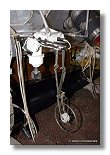
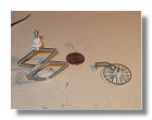
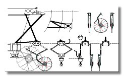 The final contribution to the construction of the Lunokhod model was the odometer/penetrometer device. Some parts were actually built in
parallel with the lid. The odometer was used to measure the travelled distance, since Lunokhod did not have any steering systems the way to go
right or left was by stopping the right wheels (if you wanted to go right) or the left wheels (if you wanted to go left), much like a tank. It implied
that the wheels could not be used to measure distance so a ninth wheel was necessary, this wheel however was not used when Lunokhod was
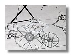
turning which explains why there was the possibility to lift it. The penetrometer was used to measure the soil resistance. The blueprint for he
odometer/penetrometer system is shown in figure 1.
The final contribution to the construction of the Lunokhod model was the odometer/penetrometer device. Some parts were actually built in
parallel with the lid. The odometer was used to measure the travelled distance, since Lunokhod did not have any steering systems the way to go
right or left was by stopping the right wheels (if you wanted to go right) or the left wheels (if you wanted to go left), much like a tank. It implied
that the wheels could not be used to measure distance so a ninth wheel was necessary, this wheel however was not used when Lunokhod was
turning which explains why there was the possibility to lift it. The penetrometer was used to measure the soil resistance. The blueprint for he
odometer/penetrometer system is shown in figure 1.
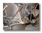
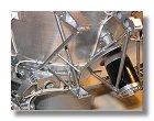
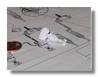
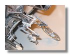
The first thing to do was to built the support sturcture, I had to glue the main strut to be able to assemble the secondary struts. In this process it
was also necessary to remove a small strut between the RTG heat shield and the lid support strut, oherwise it would have been very difficult to
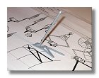
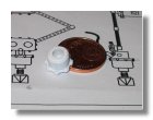
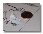
install the odometer/penetrometer support structure (figure 2). The support structure received its primer coat (figure 3) and was then painted and assembled, the small strut was back on the RTG heat shield
as shown in figure 4.
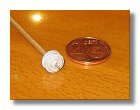
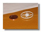
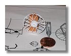
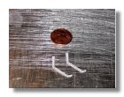
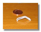
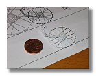
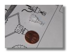
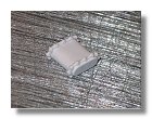
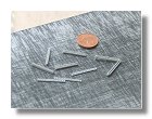
I then built the odometer wheel out of styren as shown in figures 5 and the odometer fork as shown in figures 6. This was followed by the penetrometer as shown in figures 7 and the lifting motor in figures
8.
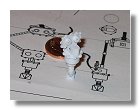
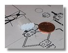
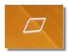
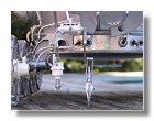
The last stage of the construction prior to painting was building the girders between the lifting motor and the odometer and penetrometer. It was a very detailled work that required patience (for most of the
parts I used 0.25 mm styrene sheets); it was very important to wait at least 30 minutes after each gluing to be absolutly sure that all pieces would stay in place. The construction process is shown in figures
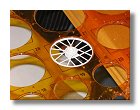
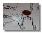
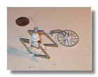
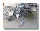
9. The various parts were then painted either in flat aluminium or white satin and assembled as shown in figures 10. The final completed penetrometer and odometer is then shown in figures 11. It is to be
noted that even my small enterprise was delocalized for this particular part since most of it was made in China when I spent 10 days in Beijing for a coordination meeting between the various space agencies
of the World (it's a good way to spend your lonely evenings far away from home).
|
|
|
|
|
|
|
Fig 2 : Support structure assembly - September
2005 |
Fig 3 : Application of surface primer - September
2005 |
Fig 4 : Completed support structure - September
2005 |
Fig 5a, b, c, d : Contruction of the odometer wheel - October 2005 |
|
|

|
|
|
|
|
Fig 6a, b, c, d : Construction of the odometer fork - October 2005 |
Fig 7a, b, c : Construction of the penetrometer - October 2005 |
|
|
|
|
|
|
|
Fig 7d, e : Construction of the penetrometer - October 2005 |
Fig 8a, b, c : Construction of the lifting motor - October 2005 |
Fig 9a, b : Construction of the girders - October 2005 |
|
|
|

|
|
|
|
Fig 9c : Construction of the girders - October
2005 |
Fig10a, b, c : Penetrometer and odometer assembly - October 2005 |
Fig 11a, b, c : Completed penetrometer and odometer - October 2005 |
Blueprints and Photographs by Vincent Meens - July - October 2005
Front page - Wheels - Chassis - Assembling - Body - Details - Cameras - Antennas - Laser reflector, instruments - RTG - Lid - Odometer & Penetrometer - Moon base - Completed Model