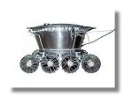
Front page - Wheels - Chassis - Assembling - Body - Details - Cameras - Antennas - Laser reflector, instruments - RTG - Lid - Odometer & Penetrometer - Moon base - Completed Model
Detailling the Chassis and the Body
The next step of the Lunokhod construction will be to install all details on the chassis and the body. A lot of these details are connectors with various systems implemented around the
Lunokhod. Since those systems are not built yet the connectors will be built but the cables themselves will be partly implemented in the construction process. Four blueprints have
been produced that detail the placement of the connectors around the chassis and the body (see figures 1, 2, 3 and 4). It is worth noting that from one model to the other it is difficult
to hcave an accurate positioning of the connectors as well as the size of these which can vary from one model to the other. The blueprints represent then a good and reasonable
compromise between all possible versions.
|
|
|
|
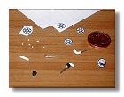
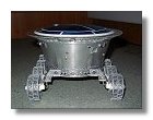
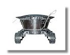
I decided then to start building details for the front part of the Lunokhod using cardboard and balsa wood, these being built were then painted in silver color (Revell 91) except for the large square part which was covered with aluminium foil (see figures 5). All those first details were then intalled onto the body and the chassis using superglue (see figure 6).
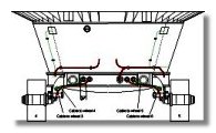
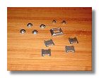
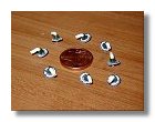
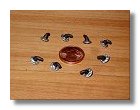
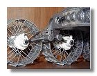
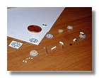
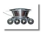
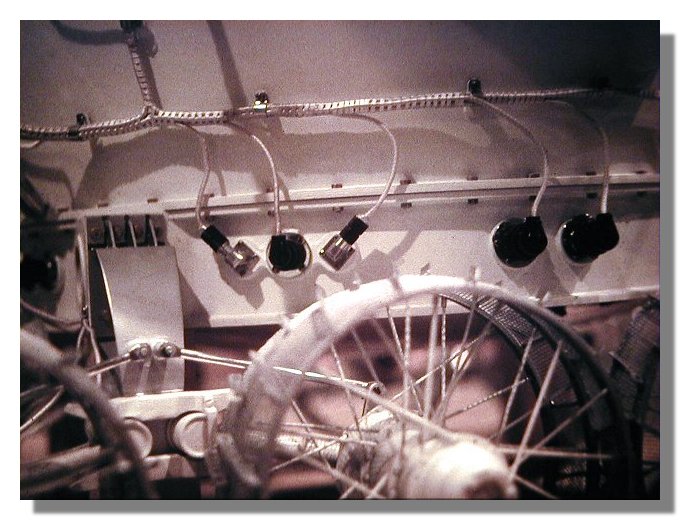
As shown on the blueprints there are two types of connectors, either small ones or large ones. I started to build the small connectors that are used for the wheel motors. The contruction process is shown in figures 7a to 7c, a 1euro cent coin is also shown to give a sense of the scale. Figure 7a shows from left to right and from top to bottom all the steps used in the construction process. Once the eight connectors for the front wheels were built and painted they were then assembled onto the chassis and the wheel motors (figures 8). Cables were then assembeld to connect the front wheel motors and the chassis (figures 9).
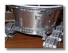
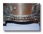
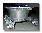
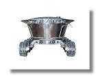
I then built the large connectors. The contruction process is shown in figure 10, a 1euro cent coin is also shown to give a sense of the scale. As for the small connectors figure 10 shows from left to right and from top to bottom all the steps used in the construction process. On this picture, construction of the Soviet Coats of Arm is also shown. In figure 11 details for the front side are installed.
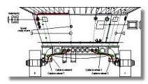
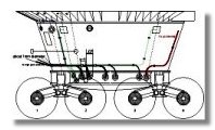
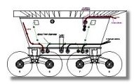
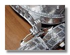
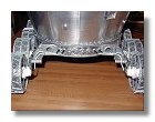
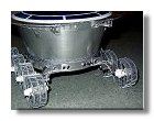
Installation of the connectors and cables for the back wheels are then shown in figures 12 and 13. Eventually, all details, connectors and cables are installed onto the chassis and body, this is shown in
figures 14a to 14d. The cable will be connected later to various devices around the lunokhod body.
|
|
|
|
|
|
Fig 5a,b : First details, connectors & antenna adapters - June 2003 |
Fig 6 : Fixing the details onto the chassis and the body - June 2003 |
Fig 7a, b, c : Assembling and painting the small connectors - June 2003 |
|||
|
|
|
|
|
|
Fig 8a : Fixing the small connectors onto the chassis and the front wheels - June 2003 |
Fig 8b : Fixing the small connectors onto the chassis and the front wheels - June 2003 |
Fig 9a, b : Fixing the cables between the chassis and the front wheels - June 2003 |
Fig 10 : Assembling the large connectors and the Soviet Coats of Arm - June 2003 |
Fig 11 : Assembling the details on the front side : June 2003 |
|
|
|
|
|
|
|
Fig 12 : Fixing the small connectors onto the chassis and the back wheels - June 2003 |
Fig 13 : Fixing the cables between the chassis and the back wheels - June 2003 |
Fig 14a, b, c, d : Fixing all connectors details and cables - anticlockwise views from the front side to the right side - June 2003 |
|||
Photographs and blueprints by Vincent Meens - June 2003
Front page - Wheels - Chassis - Assembling - Body - Details - Cameras - Antennas - Laser reflector, instruments - RTG - Lid - Odometer & Penetrometer - Moon base - Completed Model