Front page - Wheels - Chassis - Assembling - Body - Details - Cameras - Antennas - Laser reflector, instruments - RTG - Lid - Odometer & Penetrometer - Moon base - Completed Model
Radio-isotopic Thermal Generator
 The model being now more than 80% completed, one of the last steps was building
the Radio-isotopic Thermal Generator or RTG. Since the support structure of the RTG
was also supporting the lid then its construction would follow that of the RTG.
Construction of the odometer (ninth wheel) and penetrator would then be the last part
to build.
The model being now more than 80% completed, one of the last steps was building
the Radio-isotopic Thermal Generator or RTG. Since the support structure of the RTG
was also supporting the lid then its construction would follow that of the RTG.
Construction of the odometer (ninth wheel) and penetrator would then be the last part
to build.
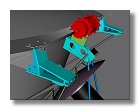
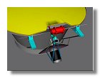
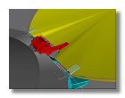
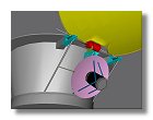
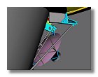
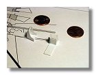
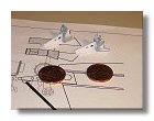
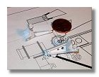
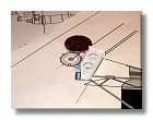
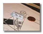
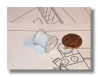
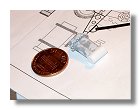
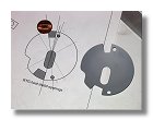
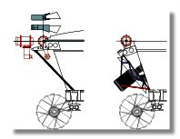
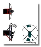
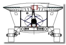
Figure 1, 2 and 3 are blueprints of the RTG. Because of the interaction between the RTG support structure and the lid, I decided to make a 3D model of both parts that could be used to help building both the RTG and the lid; 3D model pictures are show in Figures 4. Figures 5 shows the start of the construction process for the lid supports. These parts need to adapt to the previously built parts of the lunokhod which explains why both parts in figure 5a are not exactly identical and may look a bit unfinished. This was corrected by adding putty to smooth all imperfections. Then I put some primer (figure 6), painted the part in chrome and installed it on the main body. (figure 7).
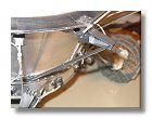
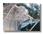
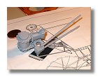
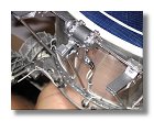
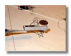
Construction of the lid motor support structure is shown on figures 8. Figures 9 show the construction of the lid motor itself, note that the rod shown in figure 9b is used as the rotation axis for the lid, it allowed to perfectly aligned the lid motor with the rotation points of the lid supports since the lid is rotating aroud these three points. This was very helpful in fixing the motor onto its support (figure 10) and also fixing the support onto the lunokhod body. That axis was eventually removed from the model.
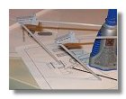
The lid motor connector was then built as shown in figures 11. It was then assembled onto the lid motor along with the struts later used for fixing the RTG (figures 12). A surface primer was then applied (figure 13) prior to paint the whole part in chrome and fixing it onto the Lunokhod body (figure 14).
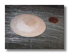
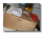
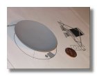
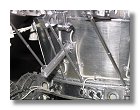
I then constructed the RTG heat shield. This was my first attempt at vacuuforming. I started by building a pattern out of balsa wood and used 0.5 mm styren sheet using a simple wood box connected to my vacuum cleaner as a vacuum forming table. I put the styren sheet directly over the patten and used a camping gaz burner to heat the styren directly. The result was quite effective and quick. The only problem I had was that the plastic shape now contained all the imperfections of the balsa pattern. I corrected these imperfection with putty using primer to check whether the shape was perfectly smooth. I then cut the various openings. The whole process is shown in figures 15.
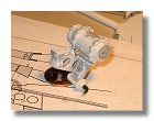
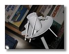
The next step was the RTG main pipe. It was necessary to built the RTG into two parts, the main pipe and the RTG itself, the reason being to have a firm fastening of the RTG onto the lunokhod body and provide an alignment for the fastening of the RTG heat shield. The process is show in figures 16. I then built the RTG itself as shown in figure 17.
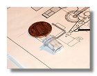
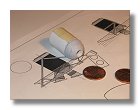
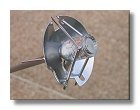
The RTG was then glued nto the heat shield. Although there is a separation in reality between the heat shield and the RTG, this is a very small separation at 1/10 scale and it would have been almost unvisible. Gluing the two pieces together had the advantage of being able to glue the various struts in place easily as shown in figure 18.
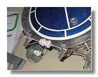
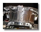
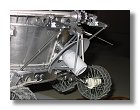
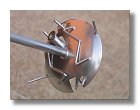
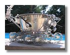
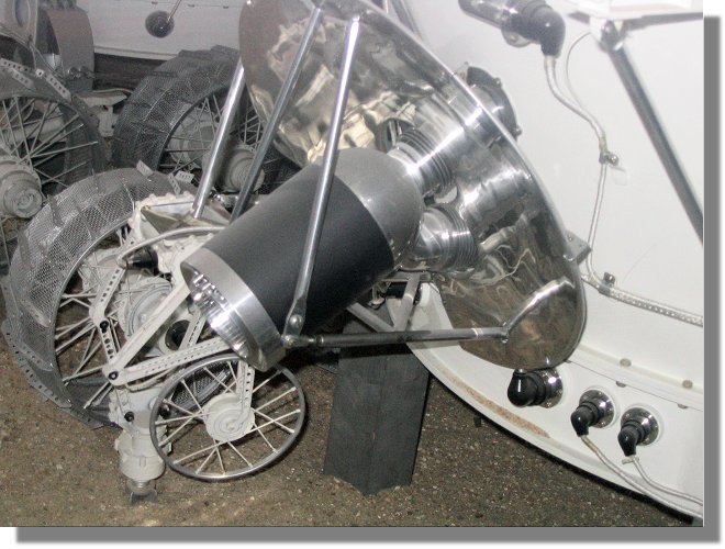
Once all struts are installed the RTG received its primer (figure 19) and was painted in chrome (figures 20) except for the center part which was stencilled and later painted in black. The completed RTG installed onto the lunokhod is shown in Figures 21.
|
|
|
|
|
|
|
Fig 4a, b, c, d, e : 3D model of RTG and lid - May 2005 |
Fig 5a, b : Construction of the lid support - July 2005 |
|||||
|
|
|
|
|
|
|
Fig 5c : Construction of the lid support - July 2005 |
Fig 6 : Application of surface primer - August 2005 |
Fig 7 : Installation of lid supports - August 2005 |
Fig 8a, b : Construction of the lid motor support - August 2005 |
Fig 9a, b : Construction of the lid motor - August 2005 |
||
|
|
|
|
|
|
|
Fig 10 : Assembly of the lid motor and support - August 2005 |
Fig 11a, b : Manufacturing of the lid motor connector - August 2005 |
Fig 12a, b : Assembly of the lid motor, connector and struts - August 2005 |
Fig 13 : Application of surface primer - August 2005 |
Fig 14 : Lid motor painted and in place - August 2005 |
||
|
|
|
|
|
|
|
Fig 15a, b, c, d : Contruction of the RTG heat shield - August 2055 |
Fig 16a, b : Construction of the RTG main pipe - August 2005 |
Fig 17 : Construction of the RTG - August 2005 |
||||
|
|
|
|
|
|
|
Fig 18a, b : Assembly of RTG, heat shield and struts - August 2005 |
Fig 19 : Application of surface primer - September 2005 |
Fig 20a, b : Application of chrome paint - September 2005 |
Fig 21a, b : Completed RTG - September 2005 |
|||
Blueprints and Photographs by Vincent Meens - July - September 2005
Front page - Wheels - Chassis - Assembling - Body - Details - Cameras - Antennas - Laser reflector, instruments - RTG - Lid - Odometer & Penetrometer - Moon base - Completed Model