Front page - Wheels - Chassis - Assembling - Body - Details - Cameras - Antennas - Laser reflector, instruments - RTG - Lid - Odometer & Penetrometer - Moon base - Completed Model
The Chassis
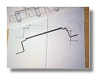
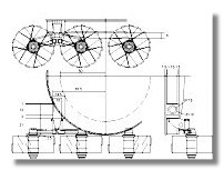
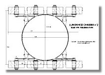
Building the chassis is the next step in the construction of the Lunokhod rover. This is a very important step since it will support all the structure of the spacecraft. We then need to build something as close as possible to the real item but also strong so that the eight wheels will support the model. For this purpose I have drawn two blueprints (see figure 1 and figure 2 besides), and as for the wheels these blue prints are in pdf format and at a scale of 1/10. Printing these drawings on an A4 paper should give you a diagram at the proper scale.
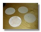
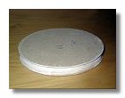
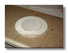
The first thing to do is to cut and assemble the various cylinders that will make the main part of the chassis. This is made out of cardboard and balsa wood of different diameters as indicated in figure 3. These parts are then assembled. the small defects are varnished and sanded using a plaster coating as shown in figure 4. It is important to note that the underside cylinder thickness is only half of what is indicated in the blueprint. This because the other half will cover the wheel support structure skeleton as shown in figure 8.
As shown in the blueprints screws are located all around the chassis, individual needle heads are then glued as indicated in figure 5 to give it the right appearance.
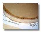
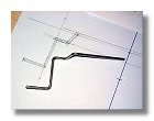
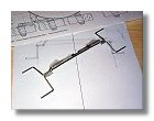
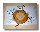
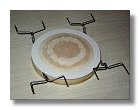
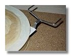
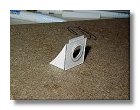
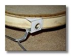
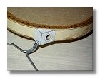
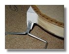
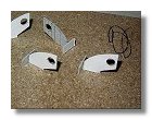
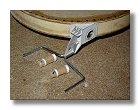
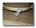
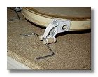
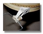
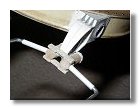
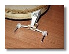
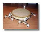
The wheel support structure appears very fragile on a 1/10 model, it is then necessary to have a stronger structure that will support the wheels and the all lunokhod model. For this I used strong piano strings to build a skeleton that will be inside the wheel support structure. Building the squelton itself is shown in figures 6. A 4 mm wide groove is made on the underside of the chassis in which the assembled squeletons are fixed using epoxy glue (figure 7).
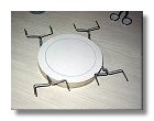
As indicated above the underside cylinder of the chassis was not as thick as mentioned in the blueprint, then an other cylinder is then glued at the base of the chassis (figure 8) and can then mask the groove and the piano string skeleton.
The underside of the chassis shows a rounded shape that is built using balsa wood cylinders of different diameters which are sanded and glued to the chassis (figures 9).
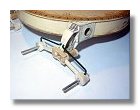
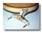
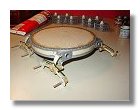
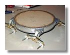
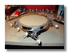
The wheels support structure is then built around the skeleton in such a way that this skeleton will almost be invisible when the wheels will be fixed (figures 10). After completion of the four structures, the
chassis is painted in silver color (Revell 91) (figure 11), to give its shiny appearance aluminium paper is used around the main part of the chassis (figures 11b & 11c).
|
|
|
|
|
|
|
3 : Cutting the main parts of the chassis - November 2002 |
4 : Assembling and sanding the chassis - November 2002 |
5 : Needle heads appear like screw on the chassis - November 2002 |
6a, b, c : Strong piano string is used as a squeleton on which the wheels will be installed - November 2002 |
7 : The piano strings are then glued onto the chassis - November 2002 |
||
|
|
|
|
|
|
|
8 : A final cardboard circle is glued onto the chassis - November 2002 |
9a, b : The underside of the chassis is made out of balsa wood which is sanded and glued - November 2002 |
10a, b, c, d : Assembling the wheel support structure - November 2002 |
||||
|
|
|
|
|
|
|
10e, f, g, h, i, j, k : Assembling the wheel support structure - November 2002 |
||||||
|
|
|
|
|
|
|
10l, m, n, o : Assembling the wheel support structure - December 2002 |
11a, b, c : Painting the chassis - December 2002 |
|||||
Photographs and blueprints by Vincent Meens, November - December 2002
Front page - Wheels - Chassis - Assembling - Body - Details - Cameras - Antennas - Laser reflector, instruments - RTG - Lid - Odometer & Penetrometer - Moon base - Completed Model