Front page - Wheels - Chassis - Assembling - Body - Details - Cameras - Antennas - Laser reflector, instruments - RTG - Lid - Odometer & Penetrometer - Moon base - Completed Model
The Wheels
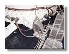
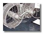
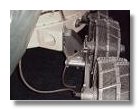
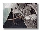
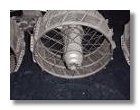
I am starting this model by the wheels, the lunokhod rover has eight wheels which are kind of very large bicycle wheels in which there are a large number of spokes. The difference with the bicycle wheel is
that it does not have any kind of tyre but instead a wire meshed rolling band. The spokes are connected to the wire mesh and the axletree. The main difficulty was to understand how the spokes were
configured. To do this I relied on photographs of models that have been exhibited around the world and in particular one that is currently displayed at the Musée de l'Air et de l'Espace in Paris. The
photographs below were taken from this full scale mockup.
|
|
|
|
|
|
|
All photographs by Pierre François "PIF" Mouriaux, February 2000
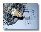
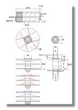 From these photographs I have produced a blueprint with dimensions in millimeters (figure 1 besides). This blueprint is available in pdf format (better for printing and reference).
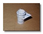
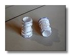
The first thing I did was to build the axletrees, they are made out of paper, in this case I used index card. It is strong enough but not too strong so I could manipulate it to form small cylinders contained in the axletrees. Figures 2a and 2b show the way these axletress were built. The main cylinder was formed with a piece of index card and both edges of the cylinder were joined using adhesive tape. All other parts of the axletrees were sticked using superglue. Once completed, the axletrees were all varnished at least twice, this allow the paper surface to be smooth in order to be painted like plastic later on.
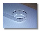
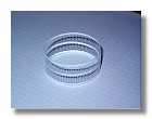
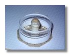
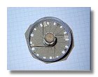
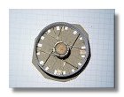
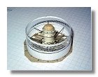
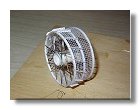
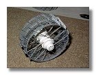
The next step was to build the rolling band of the wheel, this was done by using tulle material that is glued around the three rims. The tulle material is the best thing I have found to reproduce the wire mesh, it is slightly rigid and allows the wheels to get their definitive shape (see figures 3a and 3b).
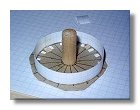
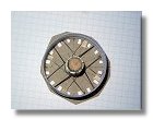
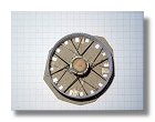
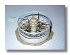
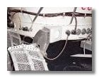
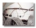
In order to install the spokes between the axletree and the rolling band, it was necessary to build a device to allow the axletree and the rolling band to be perfectly aligned with indication of the locations where the spokes were going to be sticked. Description of this system is shown in figures 4a, 4b and 4c. Figure 5 shows the rolling band and the axletree installed within this system, they were only installed and not glued so I was able to retrieve the wheel once all the spokes were in place. This device can be reused for each wheel.
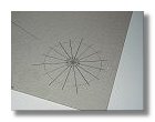
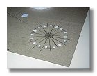
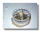
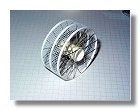
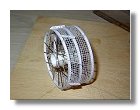
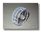
The next step was to install the spokes using the pattern defined in the blueprint, this was made from the bottom of the wheel to the top as installed in the device precedently mentioned. All spokes were individually sticked to the rims and the axletree using superglue. This was a very long process, spokes are installed by series of four as shown in figures 6a to 6f. In total there are 48 spokes to install per wheel. Figures 7a and 7b shows the completed wheel before installation of the studs.
Last but not least was the making and installation of the studs, as for the axletree and the rims they are made out of an index card and holes were pierced using a small drill. Each stud was sticked individually using superglue. The easiest way was to stick the first four studs at 90° interval on one side of the wheel, then the next four studs exactly in the middle of each pair of previously intalled studs. I did the same with the next eight studs and that way the 16 studs on one side were then installed properly. It was then easy to install all studs on the opposide side since they are all in the middle of each consecutive pair of stud of the completed side. This process is shown in figures 8a, 8b, 8c.
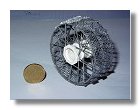
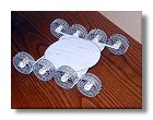
When everything was completed, painting came. The axletree is white and the rest of the wheel has a mat aluminium color (Humbrol 56) as shown in figure 9. Besides the wheel you can see a 5 centimes coin, a last chance to see this kind of coin before we use Euros in 2002. A 5 centimes coins has roughly the same size as a 1 cent coin. Building this wheel was a rather complicating process but could be achieved through patience and care. One important aspect is that after building the first wheel you need painstaking care since you know there are still seven others to build. After a while your efforts are rewarded (see figure 10).
|
|
|
|
|
|
|
2a, b : Cutting paper for the axletree and completed axletreee |
3a, b : Making of the rolling band - October 2001 |
4a, b, c : System used for the alignment of the axletree and the rolling band - October 2001 |
||||
|
|
|
|
|
|
|
5 : Rolling band and axletree in place - October 2001 |
6a, b, c, d, e, f : Process of installing the spokes between the rims and the axletree - October 2001 |
|||||
|
|
|
|
|
|
|
7a, b : Completed wheel before installation of the studs - October 2001 |
8a, b, c : Installation of the studs - October 2001 |
9 : Completed wheel - October 2001 |
10 : The eight wheels are completed and |
|||
Photographs and blueprints by Vincent Meens, May 2001 - July 2002
Following the completion of the wheels, the axles are then built. The wheels will turn around the axles and these axles will be fixed to the chassis (see the section on assembling the wheels and the chassis).
As shown in the following figures the axles will still miss the back part, this is because this will be built and installed once the wheels are fixed to the chassis.
|
|
|
|
|
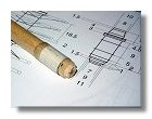
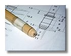
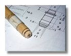
11a, b, c : The axle is sanded to give its shape as drawn in the blueprint - November 2002 |
12 : After a final sanding, a wire is glued around the axle to fix the wheel and the axle - November 2002 |
13 : The axle is finally painted in white with black dots for the screws - November 2002 |
||
Photographs and blueprints by Vincent Meens, November 2002
Front page - Wheels - Chassis - Assembling - Body - Details - Cameras - Antennas - Laser reflector, instruments - RTG - Lid - Odometer & Penetrometer - Moon base - Completed Model