Front page - Wheels - Chassis - Assembling - Body - Details - Cameras - Antennas - Laser reflector, instruments - RTG - Lid - Odometer & Penetrometer - Moon base - Completed Model
Lid
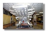
 The lid on the Lunokhod 2 had two purposes, first during the lunar day it procured electric
power through its solar cells whith which it was covered, second during the lunar night the lid was
closed and served as a further insulator (the flight model on the Moon was entirely covered with a
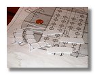
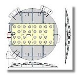
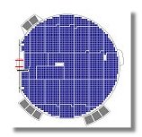
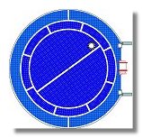
white thermal blanket including the external part of the lid). Two blueprints have been produced
(figure 1 and figure2) for the lid, figure 3 is a complementary blueprint to figure 12 of the "body"
section. It appeared from photographs I found on the novosti-kosmonavtiki web site while
researching for this part of the model that the entire top of the Lunokhod was covered with solar cells and not just the curved
part (I found these photos by googling with the word "Lunokhod" in Cyrillic alphabet). This was then corrected in figure 3.
The lid on the Lunokhod 2 had two purposes, first during the lunar day it procured electric
power through its solar cells whith which it was covered, second during the lunar night the lid was
closed and served as a further insulator (the flight model on the Moon was entirely covered with a
white thermal blanket including the external part of the lid). Two blueprints have been produced
(figure 1 and figure2) for the lid, figure 3 is a complementary blueprint to figure 12 of the "body"
section. It appeared from photographs I found on the novosti-kosmonavtiki web site while
researching for this part of the model that the entire top of the Lunokhod was covered with solar cells and not just the curved
part (I found these photos by googling with the word "Lunokhod" in Cyrillic alphabet). This was then corrected in figure 3.
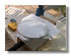
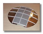
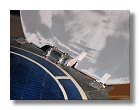
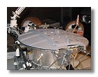
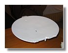
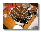
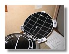
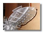
As the lid has a curve shape thermo-forming was necessary. I used two sheets of 1mm styrene which were previously assembled together side by side. From then on I thermo-formed the lid on a previously made balsa pattern. Result is shown in figure 4, one can see the line crossing the lid that shows the limit between the two sheets of stryren.
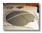
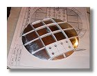
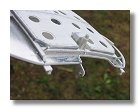
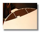
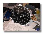
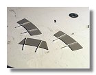
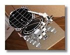
I then started to built the lid girders as shown in figures 5. I decided again to use aluminium foil on most visible parts of the lid. The chrome paint is very useful for small and tricky parts but is not easy to handle (leaving finger prints if you handle them too much and too long). Since the lid would need to be handled when moving the model, aluminium foil was felt a better choice.
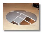
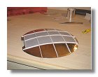
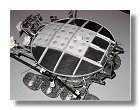
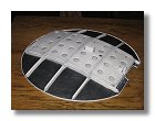
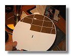
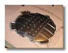
Figures 6 show the construction of the lid top cover. For this I used 0.5 mm styren sheets which were not thermo-formed but simply bended on the girders. I elevated the girders on which the top cover were to be placed by 2 mm. To give some relief on the holes I made 11 mm diameter holes in the cover and under it I glued 0.25 mm styren sheets with 9 mm holes. Eventually the bolts were glued the details were built (figure 6c).
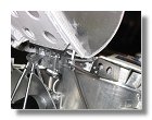
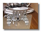
Attachments between the lid and the Lunokhod were built as shown in Figures 7. Note that I placed two pieces of rods (1 mm diameter) at the base of the lid which are used to stop the lid at an inclination of about 45°. This is not part of the real system since the inclination of the lid (depending on the sun elevation) is only controlled by the position of the lid motor. The parts covered with aluminium were then stencilled and surface primer was applied (figures 8).
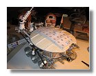
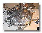
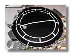
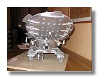
The interior of the lid was then painted in satin white (figure 9) and solar cells were applied (figures 10). For Solar cells I found a plastic thermal paper which is normally used for aircraft models (to cover wings and fuselage), this paper is black but more importantly has a square pattern which perfectly mimics solar cells. The only problem with choosing this paper was that I had to redo solar cells applied onto the Lunokhod body, previous solar cells are visible on figure 7a. Prior to assembling and painting I completed building the parts with the lid extension ones as shown in figure 11.
The back side of the lid was then painted in chrome (figure 12), the protection tape was removed and the connection cables to the solar cells were glued onto the lid as shown in figure 13. The lid extension supports were then installed (figures 14). You can note that the solar cells were changed from blue aluminium to thermal paper and completed on the lunokhod body The lid was then completed by fixing it into the body hinges (figures 15). The following picture shows the real Lunokhod 3 vs the model.
|
|
|
|
|
|
|
Fig 4 : Thermo-forming of the lid - September 2005 |
Fig 5a, b, c, d : Construction of the lid girders - September 2005 |
Fig 6a, b : Construction of the lid top cover - September 2005 |
||||
|
|
|
|
|
|
|
Fig 6c : Construction of the lid top cover - September 2005 |
Fig 7a, b, c : Construction of the lid attachments - September 2005 |
Fig 8a, b : Application of surface primer - October 2005 |
Fig 9 : White paint application - October 2005 |
|||
|
|
|
|
|
|
|
Fig 10a, b, c : Application of solar cells - October 2005 |
Fig 11a, b : Lid extensions - October 2005 |
Fig 12 : Back side painting - October 2005 |
Fig 13 : Solar cells connections - October 2005 |
|||
|
|
|
|
|
|
|
Fig 14a, b : Lid extension supports - October - November 2005 |
Fig 15a, b, c, d, e : Completed lid - November 2005 |
|||||
Blueprints and Photographs by Vincent Meens - September - November 2005
Front page - Wheels - Chassis - Assembling - Body - Details - Cameras - Antennas - Laser reflector, instruments - RTG - Lid - Odometer & Penetrometer - Moon base - Completed Model