Front page - Wheels - Chassis - Assembling - Body - Details - Cameras - Antennas - Laser reflector, instruments - RTG - Lid - Odometer & Penetrometer - Moon base - Completed Model
Cameras
 After putting the details and cables around the main body and the
chassis it is now time to build the various systems around the
Lunokhod. The first of these systems will the cameras around the
main body. There are two types of cameras, the front cameras that
are used to "drive" the lunokhod and the side cameras that were
used to take pictures and panoramas around the lunokhod. The
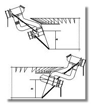
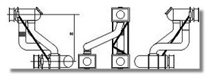
front cameras blueprints are reproduced in figures 1, 2 and 3. As you can see there are three cameras, two are at the height of a seated driver so
the pilot on Earth could see the surface of the moon as Dave Scott saw it when he was at the command of the Apollo 15 LRV. There are two
cameras to provide a stereoscopic view and then have a better impression of the surface and the obstacles. In the original Lunokhod 1 there
were only the low height cameras but it was found that for certain obstacles a view of a standing-up driver would be helpful which is the reason
for the third camera.
After putting the details and cables around the main body and the
chassis it is now time to build the various systems around the
Lunokhod. The first of these systems will the cameras around the
main body. There are two types of cameras, the front cameras that
are used to "drive" the lunokhod and the side cameras that were
used to take pictures and panoramas around the lunokhod. The
front cameras blueprints are reproduced in figures 1, 2 and 3. As you can see there are three cameras, two are at the height of a seated driver so
the pilot on Earth could see the surface of the moon as Dave Scott saw it when he was at the command of the Apollo 15 LRV. There are two
cameras to provide a stereoscopic view and then have a better impression of the surface and the obstacles. In the original Lunokhod 1 there
were only the low height cameras but it was found that for certain obstacles a view of a standing-up driver would be helpful which is the reason
for the third camera.
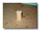
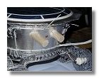
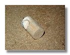
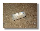
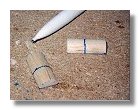
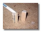
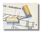
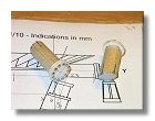
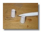
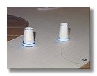
I first started to build the main camera tubes using a balsa stick having the right 1.5 cm diameter, in the center of each main tube a small piano string is glued into the cylinder and will help positionning exactly the camera onto the Lunokhod body (figure 4). Once the two main tubes are built they are positionned onto the body, then adustment must be made in order to have the tubes fitting exactly onto the body, this is done by using plaster (figure 5). Because the plaster adheres much better to the the wood of the tubes than the aluminium paper of the body, the plaster will remain onto the tubes instead of the body. Once the ajustment is made the extra plaster of the tubes is sanded and the one on the body is eliminated using a wet tissue.
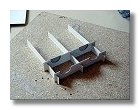
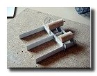
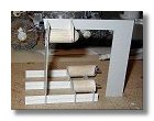
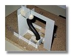
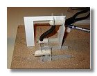
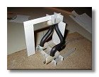
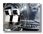
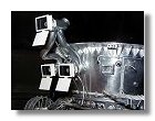
As the three front cameras are connected by two smaller tubes, it was necessary to build a support structure that allowed to maintain the three camera tubes in place while installing the connecting tubes. Construction of this support structure is shown in figures 6. The connecting tubes are made of hard electric cable (diameter about 9 mm), the three electric wires inside the cable are strong enough to keep the cable bent as wished. In order to fix this cable into the camera tube large holes needs to be drilled as shown in figures 7, then the connecting tubes are assembled using the support structure previously built as shown in figures 8.
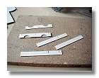
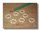
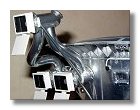
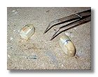
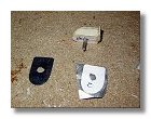
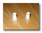
Then come the details of the cameras, the rings are first built, needle heads are used to mimic screws on the rings (figure 9). Prior to install the rings and other details it is necessary make an other adjustment of the cameras onto the body because even with the support structure previously used the relative position of the two main tubes has been slightly modified (figure 10). Finally the details are assembled onto the cameras as in figures 11 except for the lens covers. The lens covers are built separatly (figure 12) and will be installed onto the camera tubes once these are installed onto the Lunokhod body.
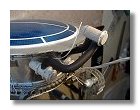
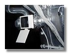
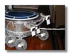
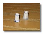
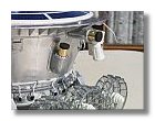
All details on the cameras having been installed, plastering, sanding and varnishing occured about four to five times before having a neat piece. It is then painted, for this I used a chrome color in a spray bottle this allowing to have a nice finish. Once done the cameras are fixed onto the body (figure 13).
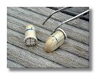
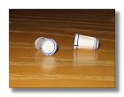
The lens covers that have been built (figure 12) are now painted, the interior being flat black and the exterior flat white (figure 14). These covers are then ajusted onto the camera tubes starting with the central cameras then the right camera and the upper one (figures 15). Although I did whatever I could to adjust all cameras using the device built in figure 6, small adjustments were still needed to make sure the lens covers were perfectly aligned one relative to the other.
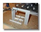
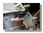
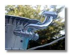
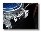
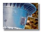
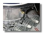
Eventually what remained was the installation of the various struts that are used to help supporting the weight of the upper camera (figures 16). Although these struts do not appear on most of the museum
models they are clearly visible on the actual model of the Lunokhod 2. Figures 17 show the completed front cameras onto the Lunokhod 2 spacecraft.
|
|
|
|
|
|
|
Fig 4 : Starting to build the main tube of the camera - July 2003 |
Fig 5 : Ajusting the two main tubes onto the body - July 2003 |
Fig 6a, b, c, d, e : Building the support structure helping to assemble and align the three camera tubes - July 2003 |
||||
|
|
|
|
|
|
|
Fig 7a, b : Making holes in the main tubes before assembling the connecting tubes - July 2003 |
Fig 8a, b, c : Assembling the connecting tubes - July 2003 |
Fig 9 : Building the camera rings - July 2003 |
Fig 10 : Ajusting the two main tubes onto the body - July 2003 |
|||
|
|
|
|
|
|
|
Fig 11a, b : Assembling the details on the camera tubes - July 2003 |
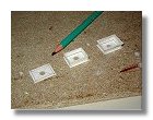
Fig 12 : Building the lens covers - July 2003 |
Fig 13 : Painting and assembling the front cameras - July 2003 |
Fig 14 : Painting the lens covers - August 2003 |
Fig 15a,b : Installing the lens covers onto the camera tubes - August 2003 |
||
|
|
|
|
|
|
|
Fig 16a, b, c, d : Installing the support struts for the upper camera - August 2003 |
Fig 17a, b, c : Completed front cameras of the Lunokhod 2 - August 2003 |
|||||
Photos and blueprints by Vincent Meens - July - August 2003
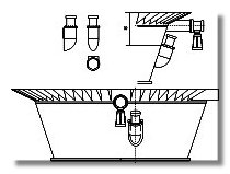
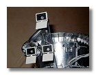
 The Lunokhod has two types of cameras, the front side that are used for piloting the rover, and side cameras that are used for taking still
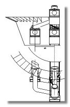
pictures and panoramas of the Moon. Figure 18 is a blueprint of the side cameras. One of the cameras can be rotated in a slightly tilted Z
axis and the other one in the Y axis. The Y axis camera is located exactly in the middle of the lunokhod body while the Z axis camera is
slightly shifted to the back. On the blueprint only the left cameras are represented, assembling of the cameras is identical for the right side
with the Z axis camera also shifted to the back of the Lunokhod body.
The Lunokhod has two types of cameras, the front side that are used for piloting the rover, and side cameras that are used for taking still
pictures and panoramas of the Moon. Figure 18 is a blueprint of the side cameras. One of the cameras can be rotated in a slightly tilted Z
axis and the other one in the Y axis. The Y axis camera is located exactly in the middle of the lunokhod body while the Z axis camera is
slightly shifted to the back. On the blueprint only the left cameras are represented, assembling of the cameras is identical for the right side
with the Z axis camera also shifted to the back of the Lunokhod body.
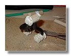
I started to work on the Z-axis cameras and first on the main camera tube. This does not look exactly like a tube because as it is applied onto the lunokhod body it is indeed half a tube that is assembled with a box. I used half balsa sticks sticked with slices of balsa (3 mm + 3 mm + 1 mm) then sanded the bottom part to get the rounded shape as shown in figures 19.
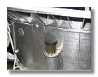
For the part supporting the camera lens, I used a tick circle of cardboard (about 1.5 mm) upon which are assembled needle heads. Once done this is glued onto the camera tube as on figure 20. As shown in figure 18, the camera tubes are not directly fixed onto the Lunokhod body, there is a thin camera binding. This is made out of paper upon which I used adhesive aluminium paper as shown in figure 21. You will also notice that as for the front cameras a small piano string is glued into the camera tube and will help positionning exactly the camera onto the Lunokhod body as shown in figure 22.
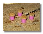
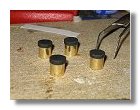
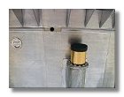
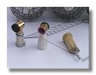
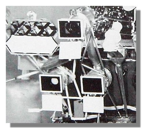
The Camera lenses are then built. I built the four lenses straight away. For this I needed 8 mm diameter tubes. Since my son has a tendency of having in his pencil case more used felt pens than usable pens, I did find one that had the right diameter and could finish its life as a Lunokhod part. As it is shown in figures 23 that was a pink felt pen. The tops of the lenses were made out of balsa wood and the main part of the lenses were covered with golden adhesive aluminium paper. Figure 24 shows the completed Z-axis camera.
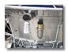
The Y-axis camera tubes were then built as shown in figures 25. This was followed by the construction of the Y-axis camera lens extension, since this part is quite small shaping is made using simple
cardboard paper as shown in figures 26. Once every pieces were built there were painted and assembled as shown in figures 27. The final result is shown in figures 28.
|
|
|
|
|
|
|
Fig 19a, b, c : Z-axis camera main tube shaping - August 2003 |
Fig 20 : Assembling the camera tubes - August 2003 |
Fig 21 : Building the camera binding - August 2003 |
Fig 22 : Painting anf fixing the camera tubes - August 2003 |
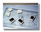
Fig 23a : Building the camera lenses - September 2003 |
||
|
|
|
|
|
|
|
Fig 23b : Building the camera lenses - September 2003 |
Fig 24 : Completed Z-axis camera - September 2003 |
Fig 25a,b : Building the Y-axis camera tubes - September 2003 |
Fig 26a,b,c : Building the Y-axis camera lens extension - September 2003 |
|||
|
|
|
|
|
|
|
Fig 26d,e : Building the Y-axis camera lens extension - September 2003 |
Fig 27a,b,c : Assembling the Y-axis cameras - October 2002 |
Fig 28a,b : Completed side cameras of the Lunokhod 2 - October 2003 |
||||
Photos and blueprints by Vincent Meens - August - October 2003
Front page - Wheels - Chassis - Assembling - Body - Details - Cameras - Antennas - Laser reflector, instruments - RTG - Lid - Odometer & Penetrometer - Moon base - Completed Model