 The
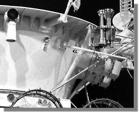
next step was to build the photodetector, only lunokhod 2 had this device.
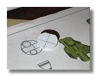
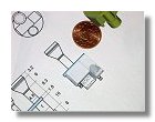
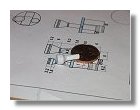
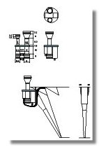
I have produced a blueprint (figure 1)
in which I have incorporated 3D views made with Gmax allowing to see precisely
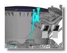
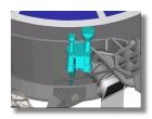
its positionning on the lunokhod body. After completing the 3D model of
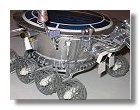
the laser reflector it was interesting to see the positioning of the photodetector
since the support structure is placed right behind one of the laser reflector
truss, figures 2 showed that the positioning was
correct.
The
next step was to build the photodetector, only lunokhod 2 had this device.
I have produced a blueprint (figure 1)
in which I have incorporated 3D views made with Gmax allowing to see precisely
its positionning on the lunokhod body. After completing the 3D model of
the laser reflector it was interesting to see the positioning of the photodetector
since the support structure is placed right behind one of the laser reflector
truss, figures 2 showed that the positioning was
correct.
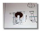
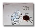
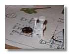
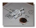
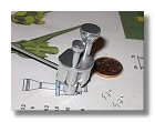
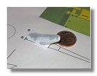
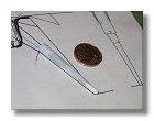
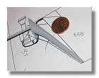
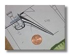
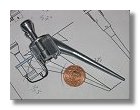
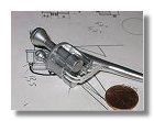
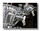
I then started to build the photodetectors themselves using only styrene sheets and tubes as shown in figures 3. I finished the contruction of the photodetectors by putting in place the small connectors using 2 mm diameter rods (figure 4). Behing the piece is an extented rod that was used for maintening the photodetectors while applying the surface primer (figure 5) and later the chrome paint (figure 6). For this I did a hole for putting the long rod but since the back of the photodetectors was glued onto the support structure this had no effect on the visual aspect of the piece.
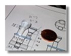
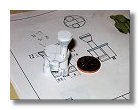
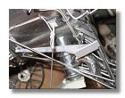
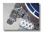
The next step was the construction of the support pylon. This was made of three parts, a rectangular plate and two conical pylons. The rectangular plate was made out of styren sheets (one 0.75 mm glued onto one 0.4 mm to get the rigt thickness). The first conical pylon was made out of 0.25 mm styren sheet and glued onto the rectangular plate. The second conical pylon was made out of several styren tubes and rods inserted one into the other to get the biggest diameter, the resulting rod was then sanded to get the proper conical shape. The two pylons were then glued together while adaptation onto the lunokhod body was checked (see figures 7). After application of surface primer (figure 8) and chrome paint (figure 9).
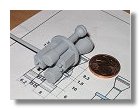
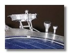
The pylon and the photodetectors were then assembled and the wires connected between the pylon and the connectors (figures 10). The final assembly was hen put in place onto the lunokhod, pictures of the completed photodetectors can be seen in figures 11.
|
Astrophotometer
|