 The
two lunokhod spacecraft had a laser retroreflector, this was the only non-Soviet
equipment since it was built by Aérospatiale in Cannes in souht-eastern
France (the place of the film festival) and resulted from the French-Soviet
cooperation aggreement in the 70's with the CNES French space agency and
the laboratory of physics of the Polytechnic School in Paris. Lunar Laser
Ranging is still conducted with the Lunokhod 2 reflector by the "Observatoire
de Côte d'Azur" in the south-east of France or the McDonald
Observatory in Texas. The Lunokhod 1 laser reflector is not working
anymore, several reasons can explain this fact : the lunokhod 1 may not
be parked properly (the retroreflector is not pointing the Earth anymore),
the lid may be closed or the lunokhod 1 location is not known with enough
precision to name a few.
The
two lunokhod spacecraft had a laser retroreflector, this was the only non-Soviet
equipment since it was built by Aérospatiale in Cannes in souht-eastern
France (the place of the film festival) and resulted from the French-Soviet
cooperation aggreement in the 70's with the CNES French space agency and
the laboratory of physics of the Polytechnic School in Paris. Lunar Laser
Ranging is still conducted with the Lunokhod 2 reflector by the "Observatoire
de Côte d'Azur" in the south-east of France or the McDonald
Observatory in Texas. The Lunokhod 1 laser reflector is not working
anymore, several reasons can explain this fact : the lunokhod 1 may not
be parked properly (the retroreflector is not pointing the Earth anymore),
the lid may be closed or the lunokhod 1 location is not known with enough
precision to name a few.
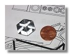
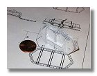
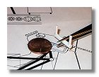
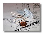
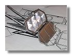
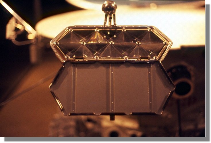
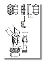
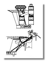
The laser reflector has a total surface of 260 cm2 and consists of 14 "cube corners" or tetrahedrons which three reflective faces are isosceles right-angled triangles. The base of the terahedrons is an equilateral triangle with each side having a dimension of about 106 mm. The peculiarity of this geometry is that whatever the direction of the laser beam, the beam will be reflected in the same direction, however to avoid loosing precious photons going back to Earth (the laser spot on the surface of the Moon is a circle of about 1km diameter) it is better if the retroreflector is facing the direction of the Earth. It is for this reason that the elevation of the reflector is about 50° as for the high gain antenna (see the demonstration under the high gain antenna section). Knowing these information has permitted to recreate a reflector which dimensions can be be well ascertained from various photos. This permitted to draw two blueprints as shown in figure 1 and figure 2.
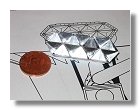
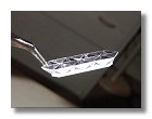
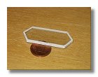
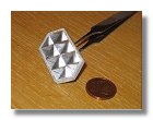
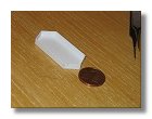
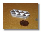
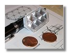
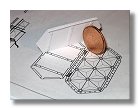
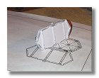
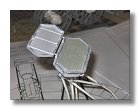
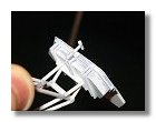
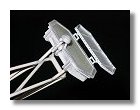
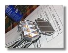
The first step was to build the tetrahedrons themselves. For this I used 0.4 mm styrene, double face adhesive tape was put onto the styrene sheet followed by mylar to give the highly reflective aspect of the tetrahedrons (figure 3). The cubes corners were then assembled, a 0.75 mm styrene base was added to make sure the terahedrons would stay in place together (figures 4). The casket which protect the reflector was then built using 0.4 mm styrene sheet (figures 5), please note on figure 5a and 5b that the white stryren part were fisrt glued onto a clear plastic sheet to protect the corner cubes.
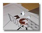
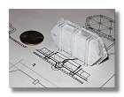
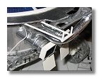
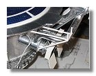
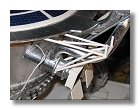
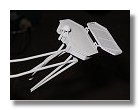
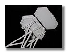
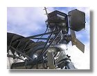
Then I started to build the reflector support structure by using 3.2 mm and 2 mm styrene rods (figures 6). This was done prior to complete the laser reflector because installing the reflector onto the support structure and making sure the position of the reflector is correct required some manipulation. It was felt there was less chance this way to break some parts of the reflector like the lid. The retroreflector was then fixed onto the structure while adding a couple of styrene rods to fix the reflector (figure 7).
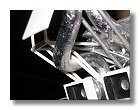
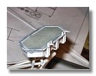
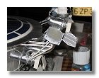
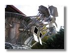
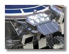
Then I built the retroreflector lid (figures 8), the hinges that connect the lid to the retroreflector itself (figure 9) and fixed the lid onto the retroreflector (figures 10), I also checked the whole assembly would fit into position as required and made the necessary adjustments on the rods. I then built the lid closing latch as shown on figures 11. Please note that the retroreflector was covered by adhesive tape to protect it for the last phase of the construction, application of primer (figures 12) and chrome paint (figure 13).
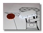
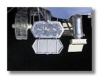
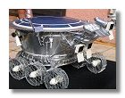
The last thing to build on the retroreflector were the mirrors fastening bolts which were made out of 0.4 mm styrene and 1mm rod and glued onto the clear plastic sheet (figure 14). Once this done the laser retroreflector was finally assembled onto the lunokhod with the last rods of the support structure (figures 15).
A special thank to Jean-Marie Torre and Jean-François Mangin from the "Observatoire de Côte d'Azur" for their precious help in designing the laser retroreflector for this Lunokhod 2 model.
|
Photodetectors
|