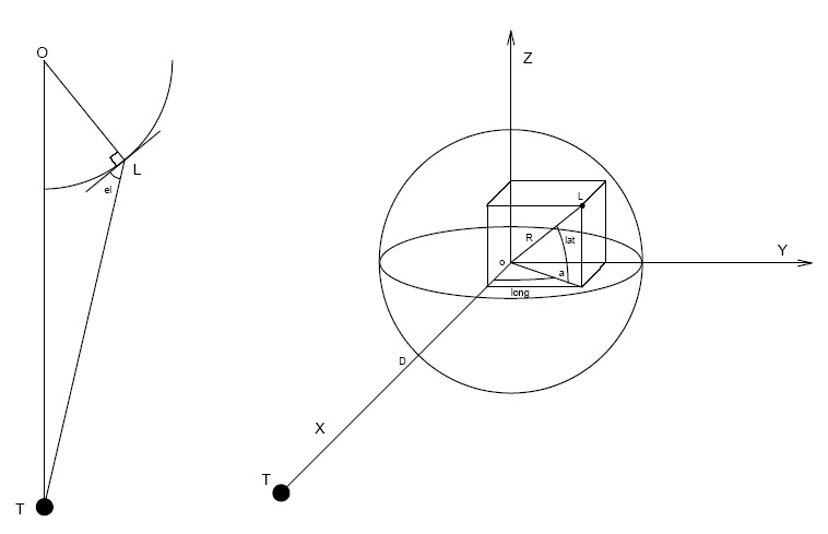
Fig 15 : Moon - Earth - Lunokhod 2 Geometry
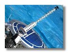
Once the antenna motor was built and fixed onto the Lunokhod body, I started to build the high gain antenna. This antenna would be separate from the motor for one reason, transportation of the model. Because of the elevation of the antenna on the moon about 50° this would imply a higher box. I then decided for it to be removable. But let's first see how the 50° elevation can be determined.
Fig 15 : Moon - Earth - Lunokhod 2 Geometry
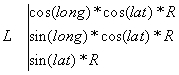
Figure 15 shows the geometry of the Earth (T), the moon (O) and the Lunokhod 2 spacecraft (L). The lunokhod position is determined by its lunar longitude (long), its lunar latitude (lat) and the moon radius (R). In a cartesian reference system one can write the following equalities :
![]()

![]()
It is then easy to calculate the lenght of the three sides of the OLT triangle :
OL = R
![]()
OT = D
The relationship between each side side of a triangle is as follows :
![]()
This will allow to calculate the OLT angle and then the elevation angle
which will be equal to OLT - 90°. The Lunokhod 2 position is 25.85
degrees N (long = 25.85) and 30.45 degrees E (lat = 30.45), the moon radius
is 1738 km (R = 1738) and the mean distance between the earth and the moon
is 384 400 km (D = 384 400). The results are as follows :
XL = 1348.36 km, YL = 653.28 km, ZL = 880.79 km, LT = 383053.21 km, OLT = 140.71°, elevation = 50.71°
This calculation shows that the elevation angle of the antenna will be about 50°. This of course is a mean value and is only valid if the lunokhod is operating on flat terrain, this may also vary in time between the apogee and the perigee of the moon, but for a model this can be considered as a representative value. This 50° elevation angle will also need to be kept in mind when constructing and assembling the laser reflector.
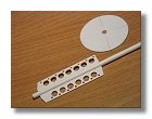
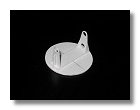
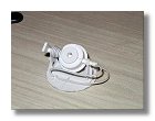
The first step of the antenna construction was
building the support for the hellix, for the main holes I used a punch
which worked very well on styrene and gave a clear cut, for the small holes
I used a small drill, the tiny holes having the same dimension as the hellix
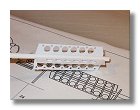
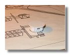
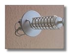
diameter (figures 16). Once this was done, the
hellix was then installed, this was quite a delicate process for which
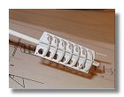
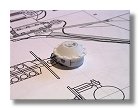
I used small telephone wire (figure 17). The 12
elements of the antenna are finally installed (figure
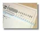
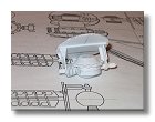
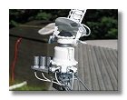
18). The back panel of the antenna was then constructed (figure
19) followed by the antenna elevation motor (figures
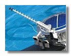
20). Once completed the elevation motor was assembled with the antenna
as shown in figures 21 and then painted and assembled
onto the main antenna motor (figures 22).
|
Magnetometer
|