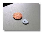
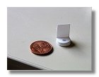
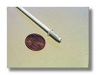
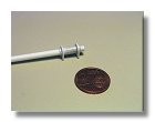
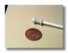
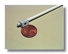
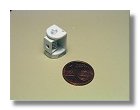
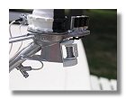

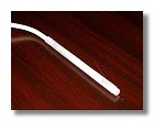
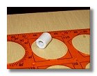
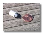
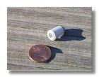
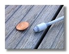
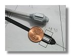
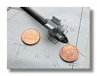
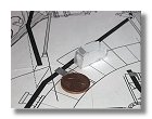
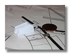
The construction then continued with the magnetometer. The first item built was the magnetometer stand, figures 23 show the construction process. Note than a 2 € cent is photographed next to the stand to give it a scale. For non-European modelers a 2 € cent has exactly the same size as a 1 $ cent. This stand was then painted and later fixed onto the high gain antenna motor (figures 24). Then the magnetometer boom was thermoformed by dipping the styrene rod into boiling water, giving it the proper shape and tempered it into cold water. The boom was then simply positioned in the stand to be sure the shape was correct (figures 25). Then followed the contruction of the magnetometer itself (figures 26). The final construction prior to assembling the magnetometer boom is the magnetometer attachment point. This allows the magnetometer boom to stay in place during launch, cruise and landing phases (figures 27).
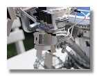
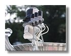
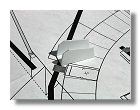
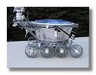
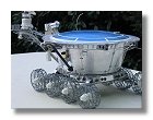
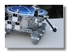
The magnetometer was finally painted in black and white and the boom
attachment point was fixed onto the lunokhod, figures
28 show the completed magnetometer in its stored position (during launch
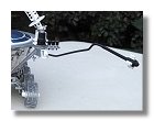
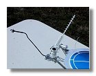
and cruise phases) while figures 29 show the
same magnetometer in its final configuration on the moon while the boom
is fully extended allowing the magnetometer to stay away from magnetic
interferences coming from the metallic mass of the lunokhod itself.
|
Conical antenna
|