If you want to model the 1/48 Lunar module you have several options as a few kits are available on the market. The only problem with these kits is that either they were designed at an early stage of the LM development or they lack accuracy. The oldest one is the 1/48 Revell model, the main dimensions are ok but the model was designed before the LM flew and shows quite a few inaccuracies like the lack of plume deflectors, various antennas or the shape of the ascent stage. The Monogram model was designed at a later stage but still shows a lot of problem, however you can build a decent accurate model if you purchase the augmentation kit from NewWare. The last 1/48 model is from Dragon but you better forget about it, the dimensions of the descent stage are totally wrong and the model looks like a cartoon figure, a small body with a big head.
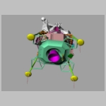
The model I propose is the most accurate 1/48 model so far, you can built it straight out of the box without any augmentation kit. Furthermore for those having a 3D printer, all parts are available on Cult3D.
You can use the instructions below to build your model or download the instruction booklets.
The plastic parts needed to build this model are available on Shapeways, however if you have a 3D printer, in particular a resin printer such as the Anycubic Photon, you can download the STL files on Cult3D and print the model at home.
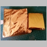
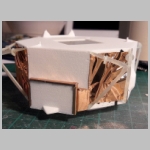
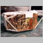
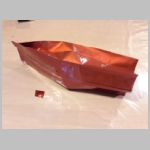
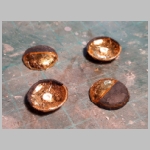
If you want a very accurate model, only very few parts will be painted since most of the LM is covered with kapton and anodized aluminium panels.
For the kapton (mainly the descent stage) you need 5 different colors :
 |
 |
 |
 |
 |
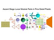 |
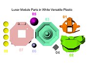
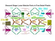
| Parts in white
versatile plastic for the ascent and descent stages |
Parts in smooth detail
plastic for the descent stage |
Parts in smooth detail
plastic for the ascent stage |
|||
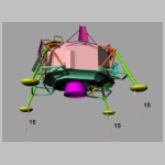
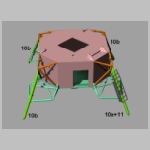
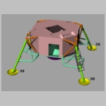
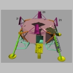
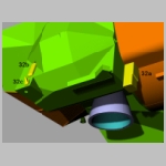
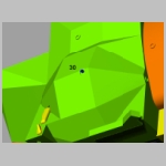
| The numbers and colors on the pdf document match the numbers on the part assembly herebelow. | |||||
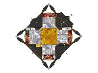
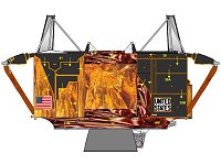
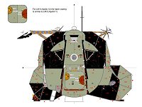
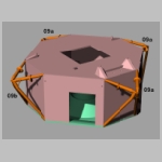
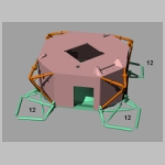
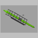
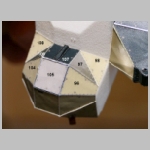
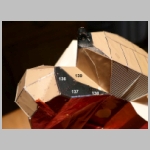
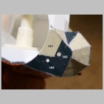
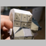
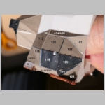
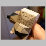
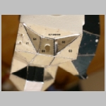
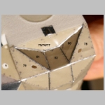
As the ascent stage and descent stage will be covered with kapton and panels the following drawing will help you to locate the various panels, blankets and shingling patterns. For the ascent stage panels I simply printed the provided sheet and applied the cutted panels on the ascent stage.
| Descent Stage Documents | ||||
 |
 |
 |
 |
 |
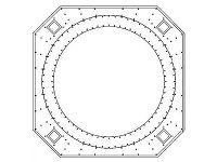
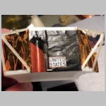
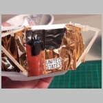
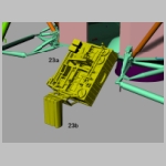
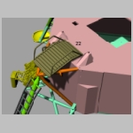
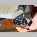
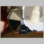
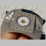
| Drawings to be used to locate the thermal blanket for LM-5 (Apollo 11). Position of the blankets might be different for other LM, please refer to Paul Fjeld coating page for further information. The middle document in this list also contains the UNITED STATES marking and US flag to be applied on the descent stage. | Pattern to be used for cutting parts around the descent engine heat shield. | Pattern to be used for kapton blankets, cutting parts around the outriggers and fixing the plume deflectors. | ||
| Ascent Stage Documents | |||
 |
 |
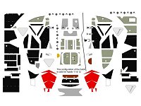 | 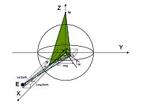 |
| Drawing showing the location of each panel on the ascent stage for LM-5 (Apollo 11) as well as the shingling pattern. | Drawing showing the location of each panel on the ascent stage for LM after Apollo 11 as well as the shingling pattern. | Patterns and decals to be used for covering the ascent stage. | This article describes the calculation behind the elevation and azimuth of the S band high gain antenna and gives for all apollo missions and each EVA the values of the elevation and azimuth angles for a correct orientation of the antenna. |
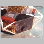
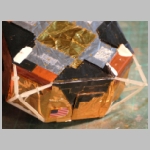
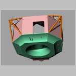
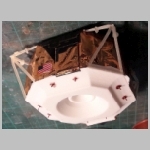
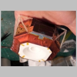
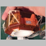
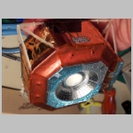
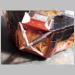
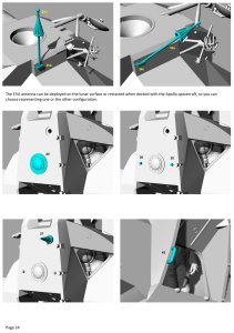
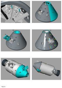
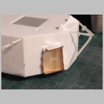
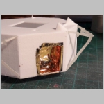
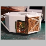
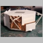
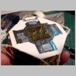
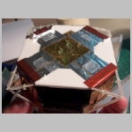
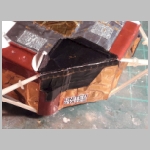
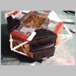
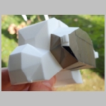
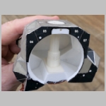
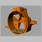
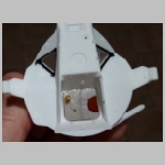
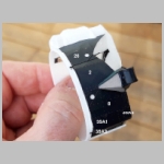
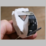
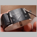
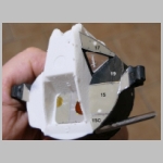
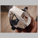
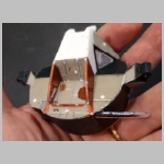
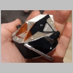
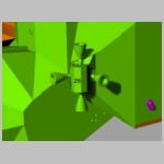
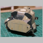
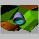
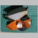
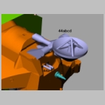
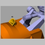
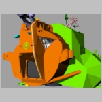
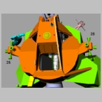
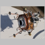
By clicking of the following pictures you will get a complete description on how to build this model.
 |
 |
 |
|
 |
|
|
 |
 |
 |
 |
 |
|
|
 |
 |
|
 |
 |
 |
 |
|
|
|
|
|
|
|
|
|
|
|
|
||||
 |
 |
 |
 |
|||
 |
 |
 |
||||
 |  |  |  |  |  |  |
 |
|
 |
 |
 |
 |
|
|
|
|
|
|
|
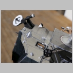
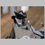
By clicking of the following pictures you will get a complete description on how to build this model.
 |
 |
 |
 |
 |
 |
 |
 |
 |
 |
|
|
|
|
|
|
|
|
|
|
|
 |  |  | 
| 
| 
| 
|
|
|
|
 |
 |
|
|
|
 |
 |
 |
 |
 |
 |
|
 |
 |
 |
 |
 |
 |
 |
|
|
|
|
|
|
|
|
|
|
|
|
|
| 
| 
| 
| 
|
 |  |

| 
| 
| 
| 
| 
| 
|
| 
| 
| 
| 
| 
| 
|
| 
|
 | 
| 
| 
| 
|
 |
 | 
|  | 
|
|
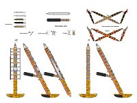
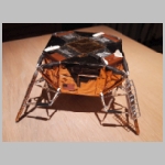
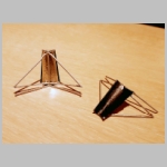
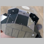
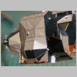
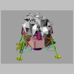
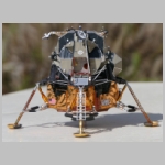
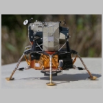
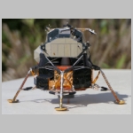
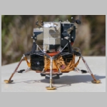
Now that the two stages are complete the ascent stage is assembled on to the descent stage followed by the landing probes
 |  |  |  |  |  |  |
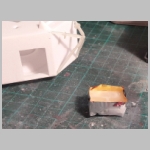
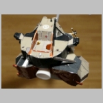
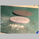
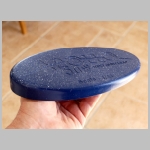
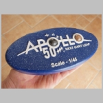
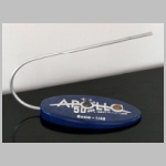
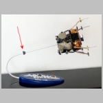
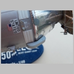
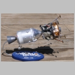
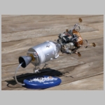
Before building the Command and Service module, I decided to build the stand. The design is based on the code 3 desk display model except that I wanted something reminding the 50th anniversary of the Apollo era so I added the official Apollo 50 logo on top of the stand.
 |  |  |  |  |
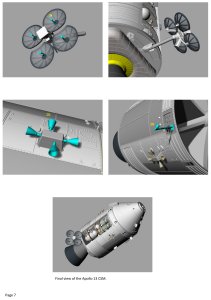
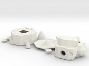
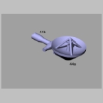
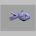
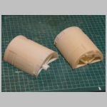
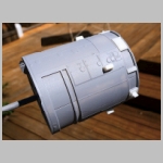
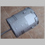
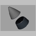
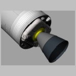
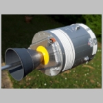
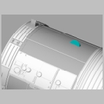
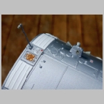
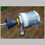
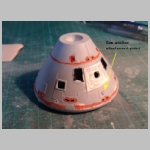
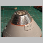
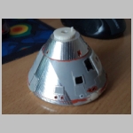
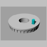
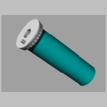
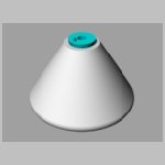
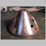
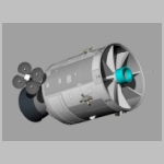
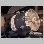
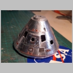
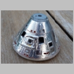
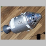
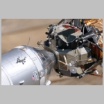
It is now time to build the Command and Service Module. For several years I had the 1/48 Realspace CSM that I wanted to use. Unfortunately I rapidly saw that the Service Module was unusable,something happened to the resin at some point and the cylinder looked like a spoiled food can . I probably could had sanded it to make it perfectly cylindrical but it meant removing all the details. I then decided to use the work I had already done with the 1/32 CSM and downscale it to 1/48. So in this model the Service module is a complete design of mine. You can download the STL files on Cult3D and print the model at home.
 |  |  |  |  |  |  |
 |  |  |  |  |  |  |
 |  |  |  |  |  |  |
 |  |  |  |  |  |  |
 |  |  |  |  |  |  |
 |  |  |  |  |  |  |
 |  |  |
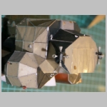
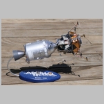
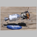
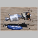
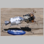
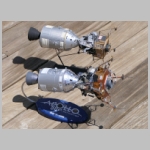
The Lunar Module and the Command & Service Modules are now linked and exhibited with the Apollo 50 stand. You can compare this model with the one I did about 4 decades ago.
 |  |  |  |  |
 |  |  |  |  |