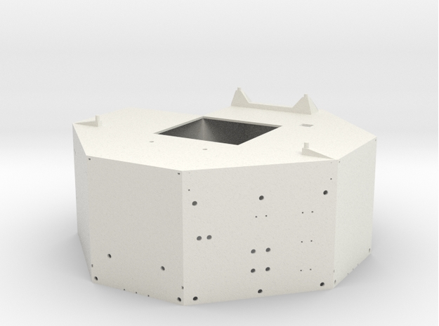
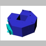
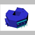
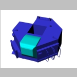
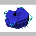
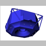
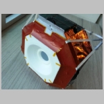
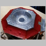
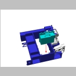
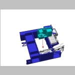
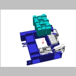
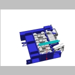
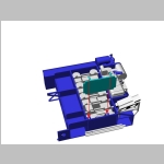
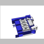
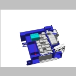
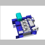
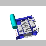
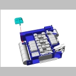
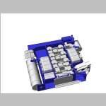
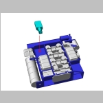
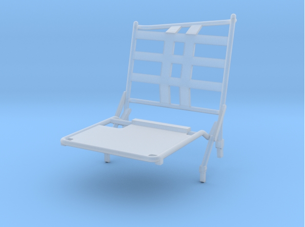
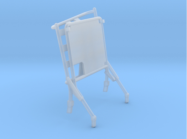
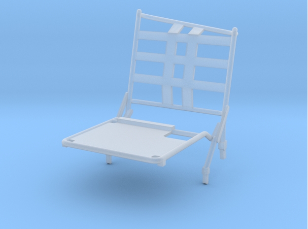
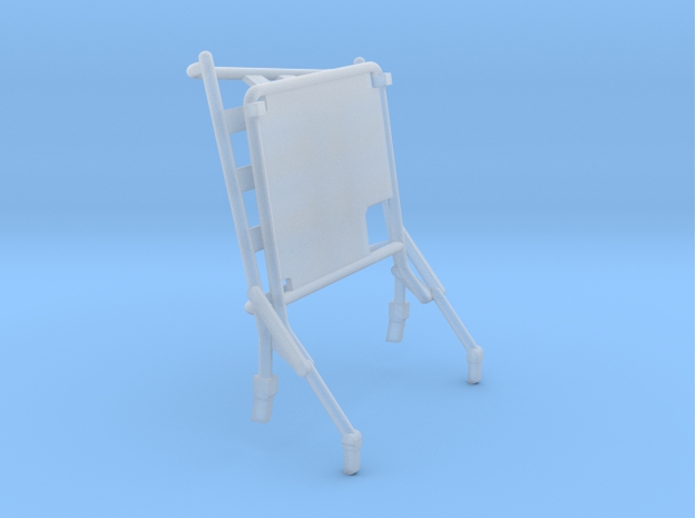
THE DESCENT STAGE, J SERIES
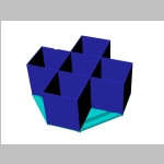
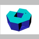
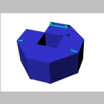
Although the general shape of the descent stage remains
identical the J version had significant differences in comparison
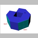
to the G and H versions. The main modfications came from the fact the
LM transported on Quad 1 the Lunar Roving Vehicle that allowed
atsronauts to travel up to 30 km on the lunar surface. For that purpose
Quad 3 carried many equipments for the LRV as well as Quad 4 with its
extended stay MESA. More subtle modifications were also needed like
relocated aft batteries to correct the centre of gravity, relocated
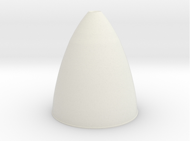
helium tanks and consequently helium vents or extended descent engine
bell to increase the engine specific impulse and the weight to carry to
the Moon.
This section will allow
you to built any LM you want between Apollo 15 and Apollo 17. If you
follow the various steps you will be able to order all individual parts
as requested by the LM you choose. However in order to make things
easier and also cheaper I combined many parts into one product which
will allow you to save money mainly on handling fees. The combined
parts are offered in Strong White and Flexible (in this case ordering
the combined product or each part individualy is about the same in
terms of price) and in Frosted Ultra Detail plastic (combining the
parts for FUD makes a great difference since the handling fees is $5
per product, so basiccaly if you combine 9 different articles into one
you save $40).
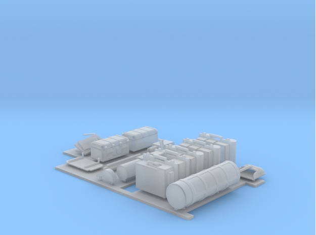
The following table depicts the combined products
you will need to buy depending on the mission you choose and its
particular configuration. In the instruction sections further down you
will be able to buy individual parts if needed.
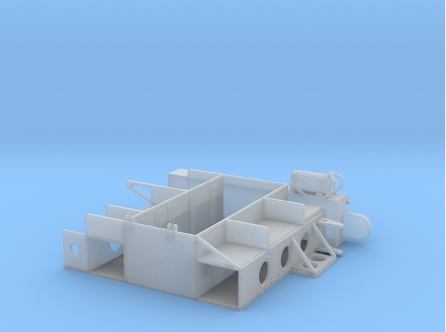
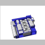
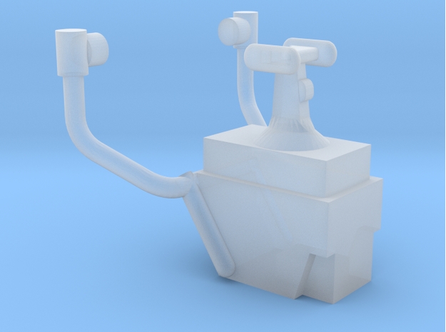
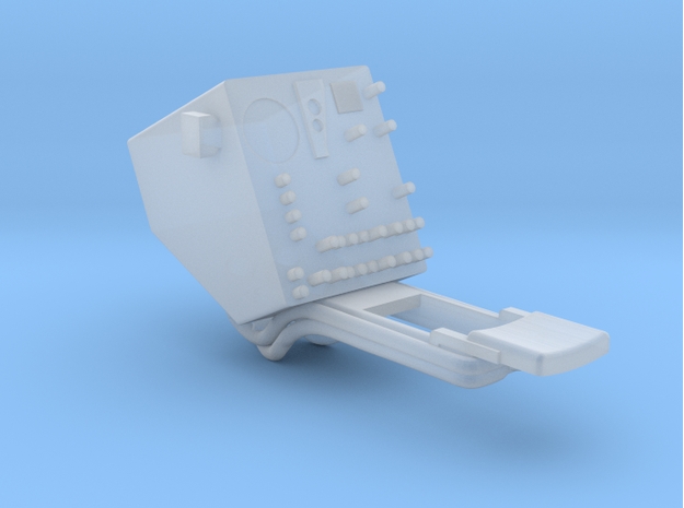
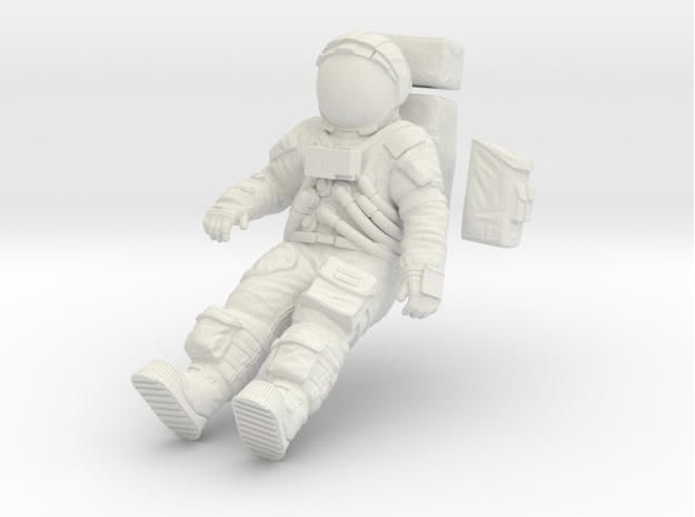
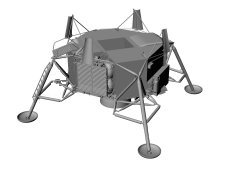
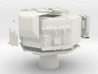
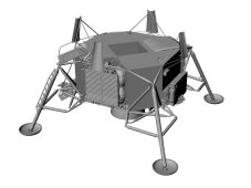
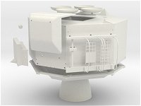
| Descent Stage with Modularized Equipment Stowage Assembly (MESA) closed - Scale 1/32 - LM in flight or just after landing |
 |   or or 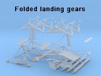   |
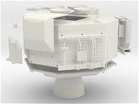
| Descent Stage with simple open MESA - Scale 1/32 - First steps on the Moon |
 |     |
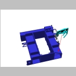
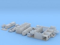
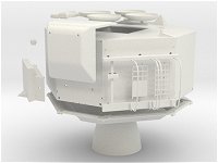
| LRV deployment scenario 1 - Scale 1/32 - LRV undeployed but MESA thermal blankets removed |
 |      |
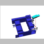
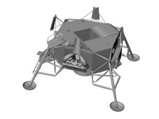
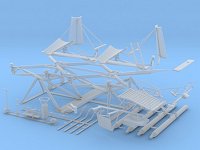
| LRV deployment scenario 2a - Scale 1/32 - Fully folded LRV deployed at 45° |
 |      |
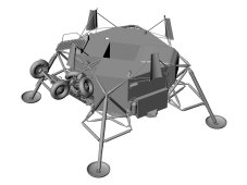
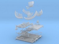
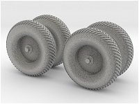
| LRV deployment scenario 2b - Scale 1/32 - Half folded LRV deployed at 45° |
 |      |
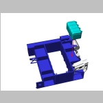
| LRV deployment scenario 3 - Scale 1/32 - Half folded LRV deployed at 90° |
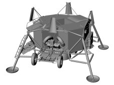 |   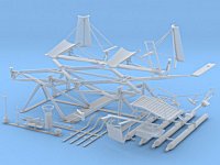   |
| LRV deployment scenario 4 - Scale 1/32 - Half folded LRV with back wheels on the ground |
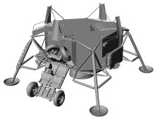 |   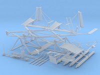   |
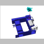
| LRV deployment scenario 5 - Scale 1/32 - Unfolded LRV with back wheels on the ground |
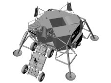 |   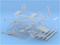 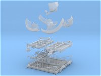  |
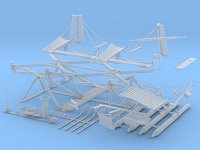
| LRV deployment scenario 6 - Scale 1/32 - Unfolded LRV, half way to complete deployment |
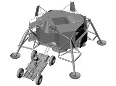 |   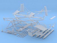   |
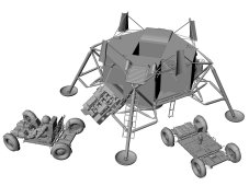
LRV deployment scenario 7 - Scale 1/32 - Fully deployed and released LRV
For
this scenario the LRV is proposed separately as it can be just
deployed, just running or fully equipped, the White Strong and Flexible
article does not contain the LRV batteries |
 |    |
Step 1 : The Descent Stage body - 1
Material :
- 1 mm / 0.04 in styrene sheet (for 1/32 and 1/24 scale)
- 0.38 mm / 0.015 in styrene sheet (for 1/24 scale)
Scale 1/32
Scale 1/24
Alternate Step 1 : The Descent Stage body - 1
Material :
Step 2 : The Descent Stage body - 2
Material :
Step 3 : Descent Stage Coating
Material :
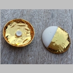
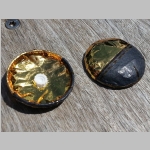
- Yellow gold survival blanket
- Orange gold survival blanket
- Aluminium paper painted in mat black
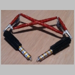
- Aluminium paper painted in metallic red brick, here is an example for the color
- Adhesive aluminium paper
- Kapton tape, here is an example
- 2 mm double sided tape, here is an example
- 1 mm / 0.04 in styrene round rod for 1/32
- 1.5 mm / 0.06 in styrene round rod for 1/24
- Satin white and flat aluminium paint
Scale 1/32
Scale 1/24
Important note : the coating pattern listed here was drawn by
Paul Fjeld who was project manager on the restoration of LM-13, this
comes from two web pages discussing the differencse between LMs (see http://home.earthlink.net/~pfjeld/lmdata/index.html), other good sources of information are :
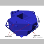
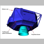
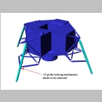
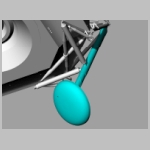
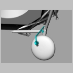
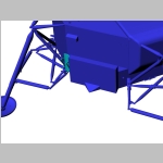
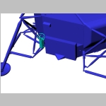
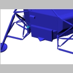
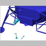
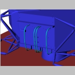
Step 4 : Descent engine, propellant drains, helium vents, landing gear uplock
Material :
- 0.75mm / 0.03 for 1/32 in, 1 mm / 0.04 in for 1/24 styrene round rod
- 1 mm / 0.04 in for 1/32, 1.5 mm / 0.06 in for 1/24 styrene round rod
- Grey, white and flat aluminium paint
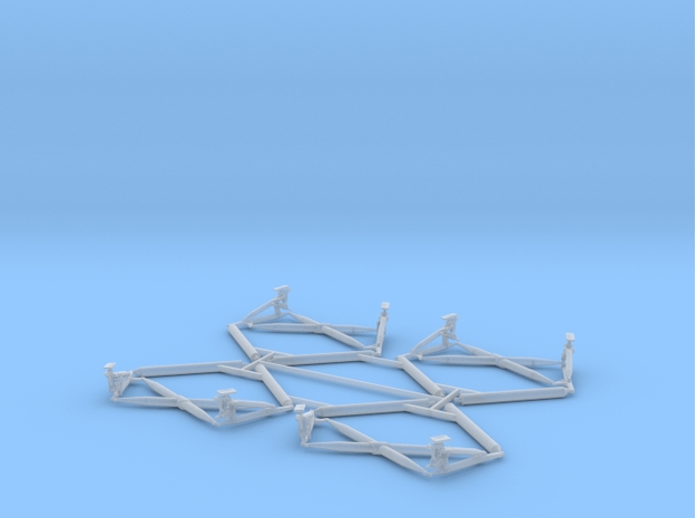
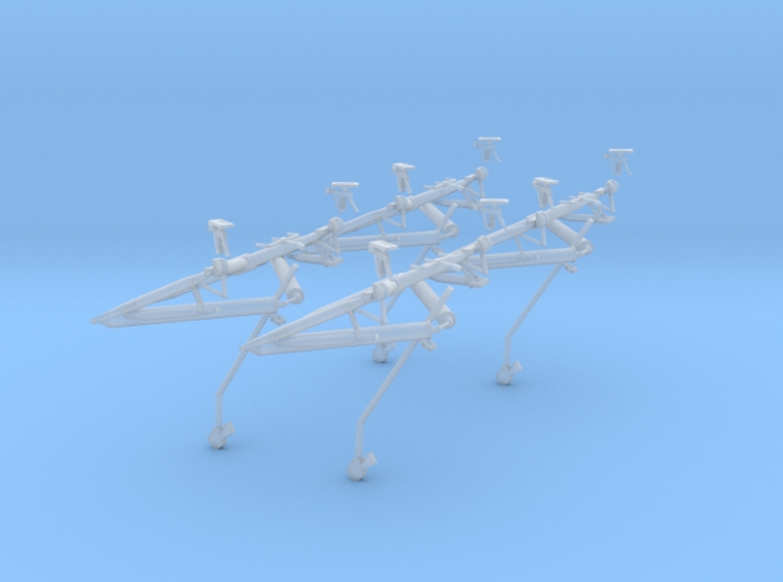
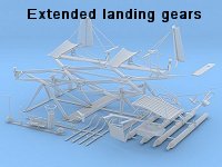
Step 5a : Extended landing gears
Material :
Step 5b : Folded landing gears
This is an alternative build if you want to show the LM either inside the SIVB stage or docked with the CSM enroute to the Moon.
Material :
Step 6 : Quad 1
Material :
Step 7 : Quad 2
Material :
Step 8 : Quad 3
Material :
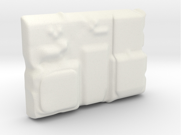
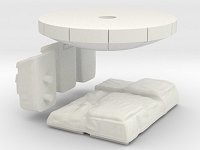
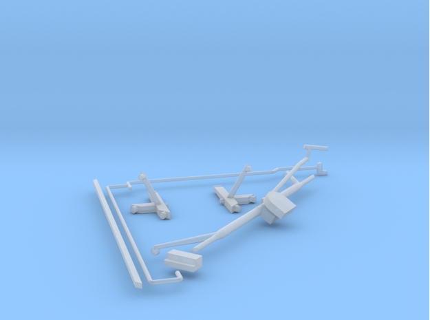
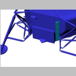
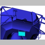
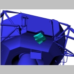
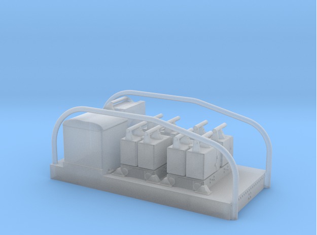
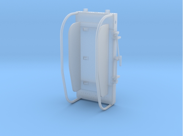
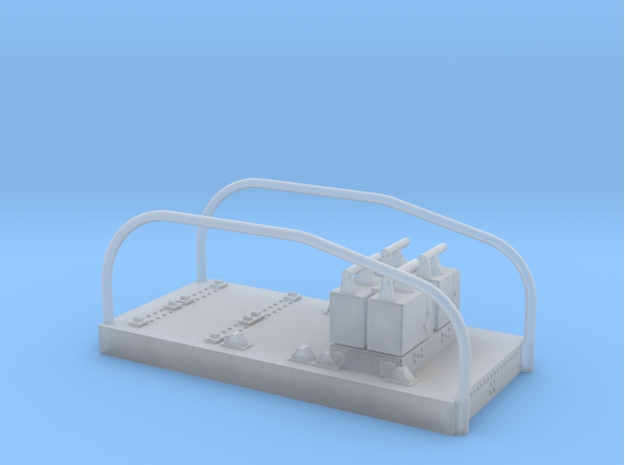
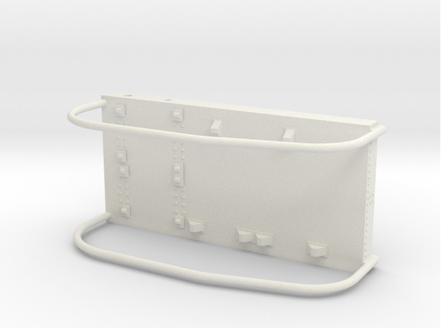
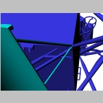
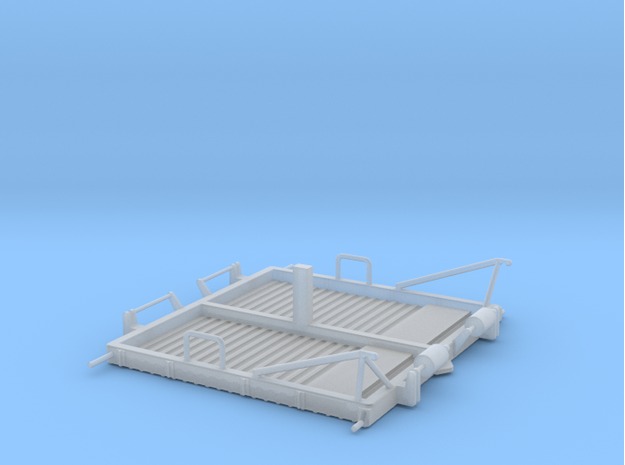
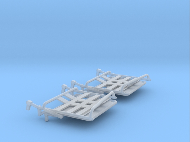
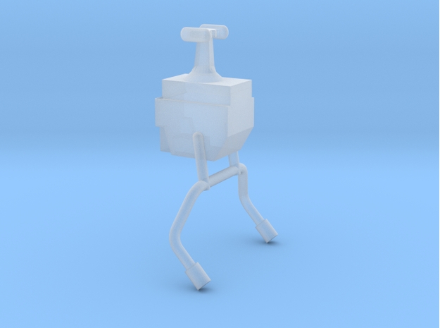
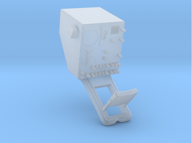
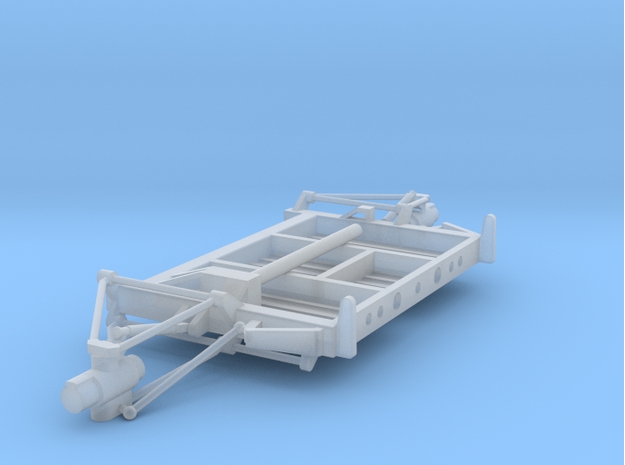
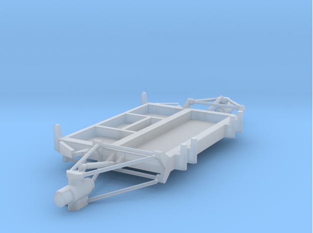
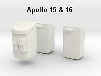
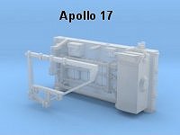
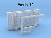
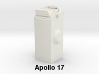
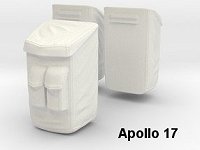
Quad 3 supported two pallets, the left one that was
removed and placed onto the aft platform of the lunar rover and the
right one contained instruments for the LRV. This last pallet was also
removed and left on the lunar surface on Apollo 15 and 17 but was kept
attached to Quad 3 on Apollo 16. Depending on the scenario you want to
depict the shapeways parts will be different. The following table gives
you an overview of the various scenarios.
Step 9 : Quad 4
Material :
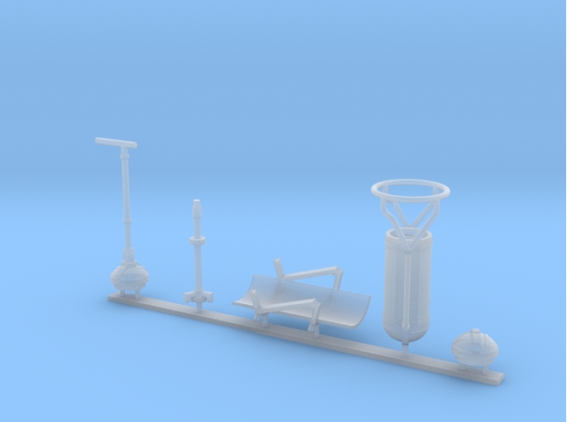
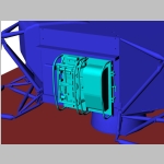
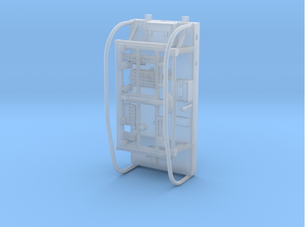
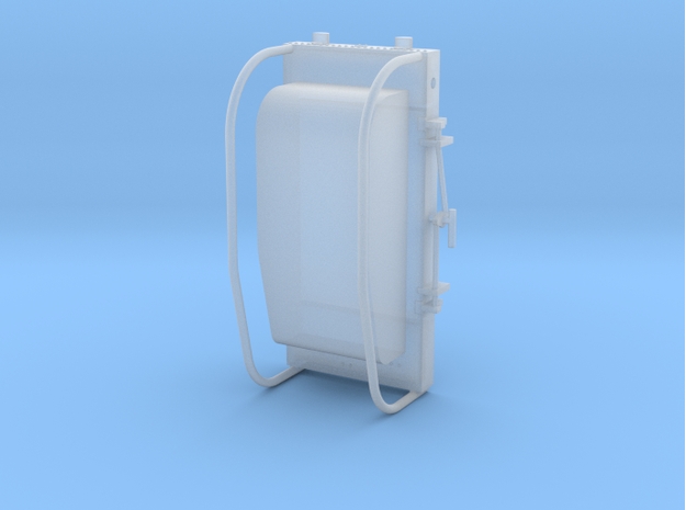
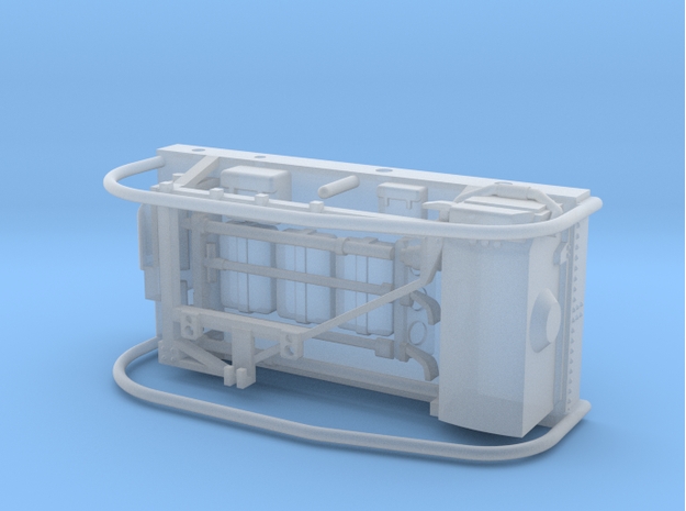
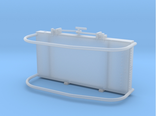
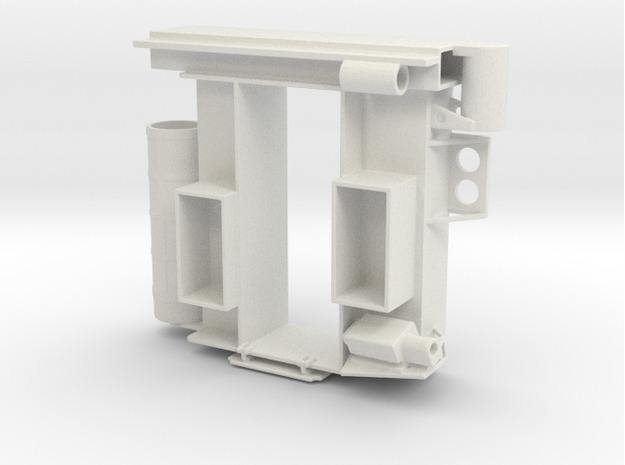
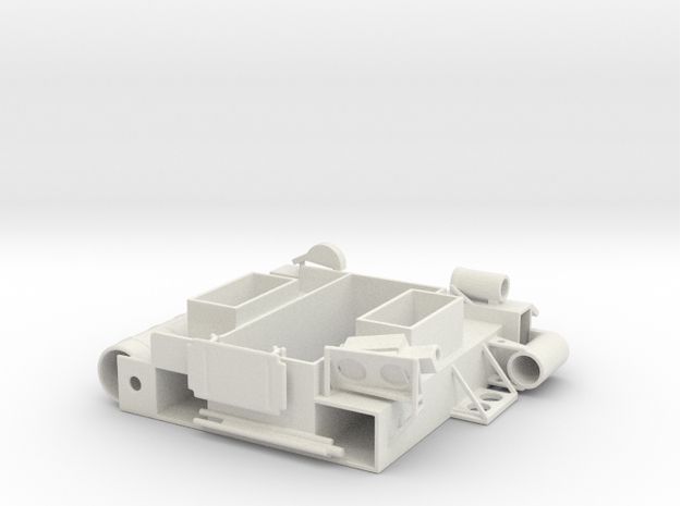
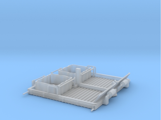
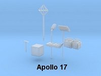
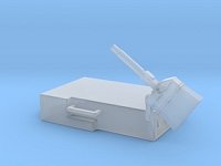
Quad 4 supported the Extended Stay Modularized
Equipment Stowage Assembly (MESA). Three scenarios are proposed, the
closed MESA, the open MESA with the thermal coating still in place
(during the first step on the Moon) and the open MESA with the
possibility to show details.
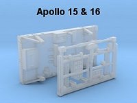
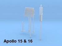
The following pictures show the construction of the
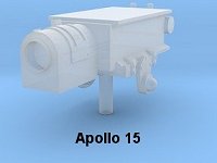
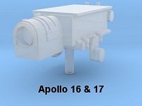
extended stay MESA. Please note the difference between Apollo 15 &
16 and Apollo17. During Apollo 17 there was no TV transmission prior to
fully deploying the Rover which means there was no support in the MESA
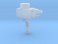
for the TV camera to film the astronauts descending the ladder. For the
same reason there was no tripod for the TV camera.
Actually the camera was used from the MESA only during
Apollo 15. During Apollo 16 there was a malfunction of the S band high
gain antenna drive preventing to transmit TV pictures. The astronauts
used the omnidirectionnal S band antennas which were only good for
voice and telemetry data.
Note that the assembly below proposes to have a
complete MESA either for Apollo 15 & 16 or Apollo 17. Depending
which part of the mission you want to depict some elements can be
removed from the MESA e.g. Sample container that can be put on the
table or LCRU and EVA pallets that found their ways onto the rover.
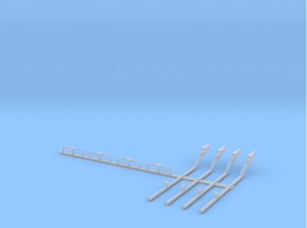
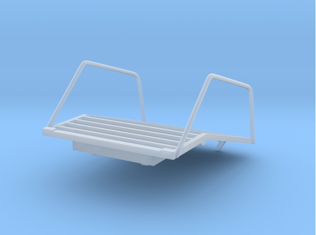
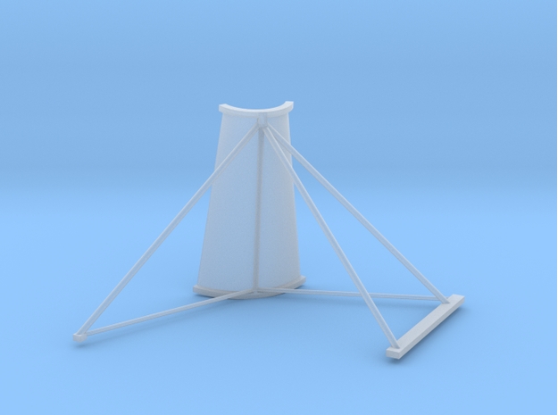
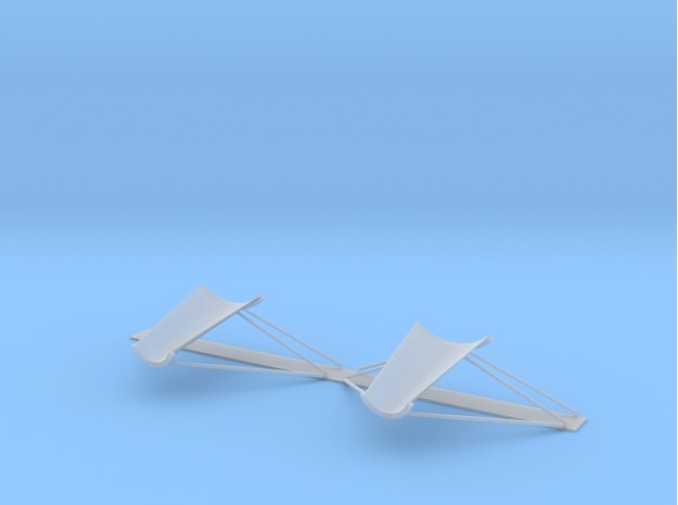
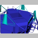
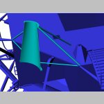
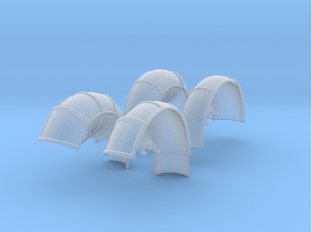
Step 10 : Egress platform and Plume deflectors
Material
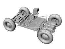
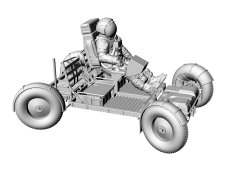
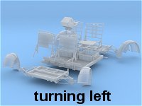
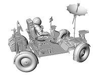
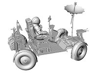
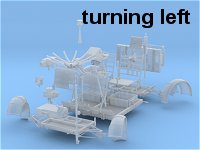
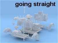
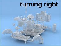
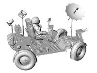
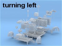
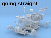
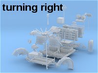
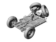
Step 11 : The Lunar Rover
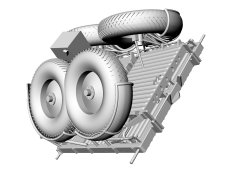
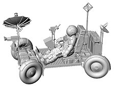
The J mission lunar modules carried on Quad 1 the Lunar
Roving Vehicle (LRV), a small electric car that allowed a giant leap in
lunar exploration. From the few 100 meters explored around the lunar
module during the Apollo 11, 12 and 14 missions the astronaut of the J
missions drove more than 30 km on the surface of the Moon. The LRV is
proposed in various configurations either during the deployment
sequence or a fully roving vehicle before the assembly of the various
elements such as the high gain antenna, the LRV pallet or the TV
camera. The first table below shows the construction of the LRV for the
various configurations while the next table shows the 10 possible
scenarios that can be modeled.
Step 12 : Fixing the LRV onto the descent stage
Following construction of the lunar rover several
scenarios are possible either with the LRV being deployed or the
operating LRV. You will need first to build the LRV and then to finish
assembling parts in Quad 1 as shown below.


 or
or 


