SOYUZ 4 - SOYUZ 5
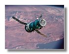
In January 1969 Soyuz 4 successfully lifted off from Launch Complex 31 in Baikonur. 24 hours later it was followed by Soyuz 5 from Launch Complex 1. Automatic rendezvous began on 16 January on the 34th revolution of Soyuz 4 and the 18th revolution of Soyuz 5. At 100 m distance Shatalov took over manual control of Soyuz 4 and guided the spacecraft to an accurate docking on the first attempt.
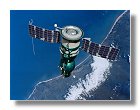
Khrunov and Yeliseyev aboard Soyuz 5 immediately began preparing for their EVA. Khrunov exited into free space and began moving toward Soyuz 4. The two spacewalkers entered Soyuz 4 without incident and after pressurisation of the orbital module were greeted by Shatalov. Soyuz 4 and 5 separated after 4 hours and 35 minutes docked together. Soyuz 4 prepared to land and the three crew successfully landed 100 km SW of Karaganda. (quote from Encyclopedia Astronautica)
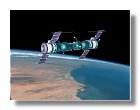
Volynov remained behind for what was undoubtedly the most unbelievable re-entry ever survived. The service module of the Soyuz failed to separate after retrofire. Once it started reaching the tendrils of the atmosphere, the combined spacecraft sought the most aerodynamically stable position - nose forward, with the heavy descent module with its light metal entry hatch at the front, the less dense service module with its flared base to the back. With every minute the G forces increased. Volynov did his duty with all of his strength but this became increasingly difficult since he was hanging in the straps of his seat with the G forces assailing him in the opposite direction from what planned. Soon a strong smell penetrated the cabin - the rubber gaskets of the hermetic seal of the hatch were burning.
He remained alive when a miracle occurred. The fuel tank of the service module finally exploded and the module separated from the re-entry vehicle. The capsule turned around to an aerodynamically stable position at hypersonic speed and the heat shield finally took the brunt of the heating as designed. The spacecraft continued on a 9 G ballistic trajectory. The damage to the capsule resulted in a failure of the soft-landing rockets. The landing was harder than usual and Volynov broke his teeth. The capsule was recovered 2 km SW of Kustani, far short of its aim point. (quote from Encyclopedia Astronautica)
The kit
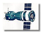
I built two New Ware 1/48 models of the early Soyuz 7K-OK, one for Soyuz 4 and one for Soyuz 5. Interestingly I noticed that I already built several 1/48 - 1/50 soyuz. When I was a kid I built Soyuz 4 - Soyuz 5, Soyuz 11 - Salyut 1, Apollo - Soyuz and more recently Soyuz TM15 within the soyuz rocket. In all I built at least 5 1/48 Soyuz and they were all scratch built. This New Ware models were my first Soyuz kits. I decided to build separatly Soyuz 4 and 5 with the possibility to show them docked if I wished to. This way it was possible to show the two male and female docking rings.
It is important to note that the New Ware kit represents Soyuz 4, i.e. the spacecraft having the male docking ring. However the kit provides for the female docking ring for Soyuz 5 but with no face details, as it is intended to be used for a Soyuz 4 - Soyuz 5 model in docked configuration only, as displayed on the box. Since I wanted to be able to show Soyuz 4 and 5 separately the female docking collar needed to be scratchbuilt.
The orbital and descent modules
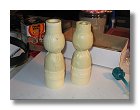
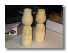
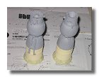
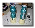
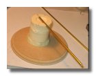
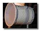
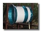
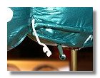
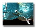
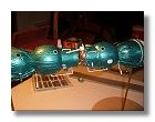
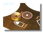
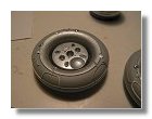
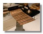
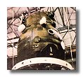
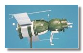
I started by fixing the Orbital module onto the descent module (168_6832), this way I could paint both orbital and descent module in the green color of the thermal blanket. I had some difficulty to find the exact color of the blanket. All photos of this model show it dark green where it is actually a combination of dark green with a touch of blue. This is quite visible on the reference photograph. Note that the dummy wheel on the right side of the 168_6832 photo (which I used to create lunar tracks for my lunokhod 2 model) is painted with the blue-green color that I used (I found a car paint to spray) for the thermal blanket.
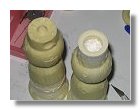
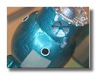
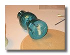
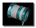
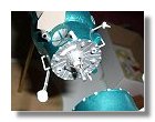
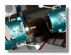
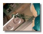
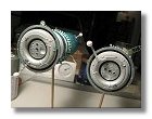
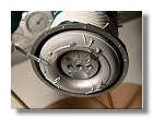
The blanketed part of the engine section was also fixed onto the service module and adjusted and the female docking ring fixed onto the docking section of Soyuz 5. Once this ring was installed it was necessary to adjust it to the correct diameter of the docking section since it was slightly larger (168_6836).
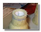
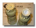
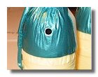
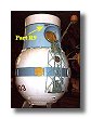
Fixing the female docking ring was not enough to modify a soyuz 4 into a soyuz 5, it was then necessary to make room for the docking cone so I had to drill a large hole within the top of the orbital module (168_6845) and then build the docking cone and latches (168_6857 to 171_7146). Besides making the female docking ring I also installed various parts on the orbital module. There are a few differences between the antennas and captors installed on both Soyuz and this is clearly indicated on the instruction sheet, however I found a small inconsistency between this sheet and the booklet on Soviet spacecraft written by Mike Mackowski.
This concerns the part R9 which is an antenna present on Soyuz 5 (the female version) as indicated on the instruction sheet, the problem is that Mike's booklet shows it only present on Soyuz 4 (the male version) and not on Soyuz 5 (the female version), for this you have to compare Fig 6 and 8 of SIM related to Soviet spacecraft. Having made some research I came to the conclusion that the instruction sheet is correct and that this antenna is indeed present on Soyuz 5 (see 171_7146 and soyouz_module_orbital_femelle_01-02.jpg).
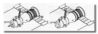
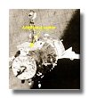
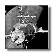
Unfortunatly the problem does not stop there, when you consider other drawings and photographs you come to realize that opposite part R6 on Soyuz 5 comes a captor of some sort on Soyuz 4 but this captor is not indicated in the instruction sheet. Part R6 is both on Soyuz 4 and 5 (see Sans-titre-2.jpg) and part R9 on Soyuz 5 is opposite Part R6 on Soyuz 4. This is first shown on a drawing of both Soyuz 4 and Soyuz 5 (Soyuz_4-5.jpg) and further confirmed with in-flight photographs of Soyuz 4 (p13096.jpg to soyuz-4.jpg). One can see that this additional captor looks more like part R9 than part R6 so the question is : if part R9 on Soyuz 5 is exactly opposite to part R6 on Soyuz 4, isn't it possible that this additional captor on Soyuz 4 is an other Part R9, in this case opposite to part R6 on Soyuz 5 which would make Mike Mackowski drawing correct as far as Soyuz 4 is concerned.
The full scale models of Soyuz 4 and 5 only show Part R9 on Soyuz 5, however I don't believe this is an antenna in a sense of communication but rather a captor to be aligned with part R6 which I believe is an optical sensor. R6 and R9 are perfectly aligned when the two soyuz are docked, so one has to wonder, if part R6 is present on both Soyuz 4 and 5 it makes perfect sense for part R9 to also be on both Soyuz. And it is probably present on both sides on the orbital module, photograph soyouz-1967-71s.jpg shows a protuberance on the hatch side on the orbital module which is probably the fixture of this captor. Furthermore photograph of Soyuz 4 in flight seems to show this captor on both sides of the orbital module. In the end I decided to include Part R9 on both Soyuz 4 & 5.
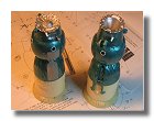
I then added this part to the orbital module of Soyuz 4 and started putting a surface primer onto the orbital and descent modules of both soyuz. This allowed to reveal tiny bubbles within the resin. It was then easy to fill them with putty and apply a new coat of surface primer. I was quite satisfied how the thermal coating looked under the primer as well as the scratchbuilt female docking collar (see 172_7207). I then applied masking tape and painted the descent and orbital modules in dark blue-green (172_7250 to 172_7257). I then completed the painting of the details, the windows and the docking probe (172-7272). There were two differences between the model and the intructions for painting. The first difference is about the window frames which are said to be white in the instruction sheet, although this is true for the orbital module detailled photographs (see Sans-titre-2) show that the frame is metallic for the descent module (172_7280 to 172_7289). The second difference is about part OM7, the instruction sheet asks you to paint it in white but photos of the actual spacecraft show that it was covered with green insulation blanket (see soyuz 1967-71) but it is true that during the Apollo-Soyuz flight this part was not covered with insulation blanket and was white (see 01).
The service module
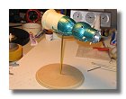
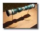
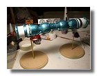
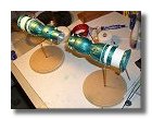
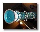
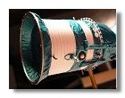
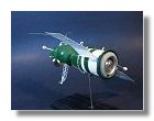
The blanketed part of the engine section was already fixed onto the service module and adjusted (168_6836) to allow later on to paint it in green and white. Before putting any details I installed a brass rod into the module which was to be used as a support for the model onto its stand. For this I had to make a groove into the service and descent modules. Once assembled the complete soyuz could be installed onto its stand for a trial (173_7343 to 175_7554). The spacecraft will appear leaning by an angle of 45° with its large rendez-vous radar in an upward position. I then glued most of the details, applied some primer and painted the module in green (the thermal blankets) and white (the radiators). For the radiator I used Tamiya flat (176_7630 to 176_7645).
Fixing the model on its base
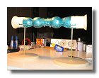
I then glued the service module with the descent module while not forgetting to include the antenna ring between both modules. I noted that the descent and service modules were not perfectly aligned so I decided to enlarge the hole at the top of the service module so there was enough play to adjust service and descent modules. Both modules were attached using epoxy resin as it dried slowly allowing for the best possible ajustment. Both models were then joined together using tape and fixed onto each base, again using epoxy (Cim0724). This way both models were perfectly aligned whether they were docked or undocked (Cim0767 to Cim0776).
Detailing the model
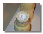
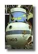
I started by installed details onto the descent and orbital modules. almost every detailed parts were painted prior to installation onto the model. For the periscope the instruction sheet indicates to paint it in light grey, however photographs of actual models show it painted in flat green. Image1.jpg shows the periscope of an exhibition model of Soyuz 4/5, although it is true that the external appearance of such model has usually nothing to do with an actual Soyuz (lack of thermal blanket in particular), in this case photo soyuz-tma2-iss-desk-1280s.jpg shows the periscope of a Soyuz TM to be of the same green color with a white thermal blanket at the bottom. I then decided to adopt the same scheme for the model as show in Cimg0793.jpg and Cimg0795.jpg. The antennas on the orbital modules were fixed (Cimg0801.jpg). and then the optical target for rendez-vous (white part on Cimg0793.jpg and Cimg0795.jpg). For the optical target I had to make sure that each one was perfectly aligned with the periscope of the other Soyuz (Cimg0809.jpg).
The docking probe required a lot of attention, the photo-etched part was tiny and needed to be bent in several places making it difficult to shape. Furthermore I needed the probe, being the male docking part, to perfectly adjust into the female part which required to slightly adjust parts R15 and R12. The result was eventually quite satisfactory as shown in Cimg0819.jpg and Cimg0821.jpg.
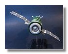
For the rendez-vous radar I first had to shape the reflector of the antenna using a ball, I first used a small ball of less than 1 cm diameter, the metal bent but the curvature was irregular. By using afterwards a 2 cm ball I succeeded in having a perfect circular shape a shown in Cimg0789.jpg. The completed radar with its antenna mast is shown in P1020264.jpg and P102270.jpg, the color of tha antenna mast and the reflector is green as shown on Sans-titre-2.jpg. It is the same green color as the one used for the periscope. I eventually completed the details by fixing the stellar sensor as shown in P1020272.jpg.
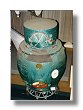
The main difficulty of the toroidal tank was painting, especially the white cables which are quite tiny on the model. I used the grey primer as the main paint for the toroidal tank and added aluminium paint for the inner wall. Then the cables were painted using the finest paintbrush and magnifying glasses. The engine defletors and the antenna mast were then added to the toroidal tank which was subsequently attached to the service module. The engine section was the final addition (see P1020279.jpg to P1020294.jpg).
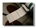
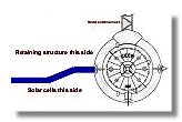
Solar panels presented no big difficulty, however one has to be very careful on how to bend the panels. The way the photoetched part is manufactured and the perspective view on the instruction sheet may lead to a panel being bended the wrong way. The retaining structure of the panel is facing the radar antenna mast and has no solar cells, the cells are opposite the radar mast on the flat side of the panel, the bending is shown in panel.jpg. New Ware soyuz have been built by other space modelers, gjsoyuz43.jpg and gjsoyuz44.jpg show a model built by Glenn Johnson with uncorrectly bended panels. The solar cells are on the retaining structure while the part facing the radar antenna mast is flat. As Glenn told himself :
"I found the instructions confusing and actually removed the panels more than once and still got them on wrong, but they are so thin, that I was afraid to change them again. So I just left them the way you see them in the photos for fear of damaging them beyond repair".
On the opposite nw009p3a.jpg and nw009p5.jpg built by Tomas Kladiva show correctly bended panels. When I bended my first panel I did it the wrong way, I corrected immediately but the flat part of the panel presented some ripples which I managed to erase by sanding and adding some putty.
I decided to redo entirely the antenna in particular the back part as I found the photoetched part too thin. I used some 0.4 mm wire to make the antenna and glued it onto the retaining structure of the solar panel (P1020306.jpg). The instruction sheet indicates that the antenna is metallic but on the exhibition soyuz the antenna is white. I know that the exhibition soyuz have usually nothing to do in terms of color with the flight soyuz but in this case, as for the radar antenna mast, I believe that the color on the exhibition soyuz is correct since the only photograph I found of a flight soyuz with this anteanna show it white (capt1.jpg). You can also note on this photo that the antenna rod is extended at the back.
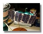
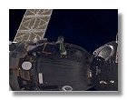
I eventually painted the panels in Tamiya Flat white, applied the decals and fixed the panels onto the service module (P1020329.jpg and P1020334.jpg).
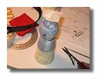
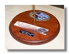
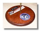
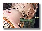
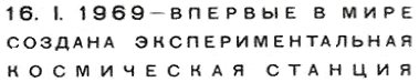
I painted the base with a mahogany varnish and included three plates. For the main plate, I found a first day envelope on the internet with the following inscription:
Using an internet translator I found the translation as :
16. 1. 1969 - For the first time in the world
The first experimental space station is created
I liked the Soviet style of the inscription so I decided to keep it. I printed it on a bronze background and added for each Soyuz a Soviet pin also bought on the internet. The mission patch was also added for each mission as shown in P1020354.jpg and P1020355.jpg.
CONSTRUCTION OF THE MODEL
|
|
|
|
|
|
|
|
|
|
|
|
|
|
|
|
|
|
|
|
|
|
|
|
|
|
|
|
|
|
|
|
|
|
|
|
|
|
|
|
|
|
REFERENCE PHOTOGRAPHS
|
|
|
|
|
|
Thermal blanket color |
R9 position |
Position of antennas/captors on Soyuz 4 & 5 |
|||
|
|
|
|
|
|
||
Additional captor |
Insulation blanket |
Periscope |
Solar panel bending |
||||
|
|
|
|
|
|
|
|
Solar panels uncorrectly bended |
Solar panels correctly bended |
Antenna color |
|
|
|
||
FINISHED MODEL
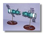
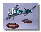
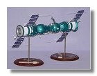
Here are some photographs I made of the finished models. As indicated in the article some parts require all your attention and sometimes the color scheme needs to be modified. Otherwise it is by far the best model of a soyuz spacecraft on the market. I really enjoyed building it. There is little room for scratch building, simply because the model is so accurate. My scratch building effort were only limited to the Soyuz 5 docking system which is not represented. A truly nice model.
|
|
|
|
|
|
|
|
|
|
|
|
|
|